CMS32L051 User Manual |Chapter 5 Universal Timer Unit (Timer4)
www.mcu.com.cn 147 / 703
5.5.3 Operation of counter
The following describes the counter operation for each mode.
(1) Operation of interval timer mode
(1) Enter the operating enabled state (TEmn=1) by writing 1 to the TSmn bit. The timer count register
mn (TCRmn) holds the initial value until the count clock is generated.
(2) Generate a start trigger signal by allowing the first counting clock (fMCK) after operation.
(3) When the MDmn0 bit is 1, INTTMmn is generated by starting the trigger signal.
(4) Load the value of the timer data register mn (TDRmn) into the TCRmn register by allowing the first
count clock after operation, and start counting in interval timer mode.
(5) If the TCRmn register is decremented to count to 0000H, INTTMmn is generated by the next count
clock (fMCK), and the timer data register mn (TDRmn) value continues to be counted after loading
the TCRmn register.
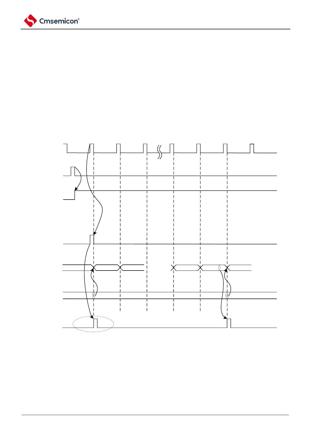
Figure 5-26 Operation timing (interval timer mode)
Note: Because the 1st count clock cycle runs after the TSmn bit is written and delays the start of counting before
generating the count clock, an error of up to 1 clock cycle is generated. Also, if information about the start of the
count timing is needed, set MDmn0 to 1 so that an interrupt can be generated at the start of the count.
Remark: f
MCK
, the start trigger detection signal and INTTMmn are synchronized with fCLK and are valid for 1 clock.