CMS32L051 User Manual |Chapter 13 Serial Interface SPI
www.mcu.com.cn 459 / 703
Chapter 13 Serial Interface SPI
13.1 Serial interface SPI function
The serial interface SPI has the following two modes.
(1) Operation Stop mode
This is a mode used when no serial transfer is taking place, which reduces power consumption.
(2) 3-wire serial I/O mode
This mode transfers 8- or 16-bit data to multiple devices via 3 wires of the serial clock (SCK) and serial
data bus (MISO and MOSI).
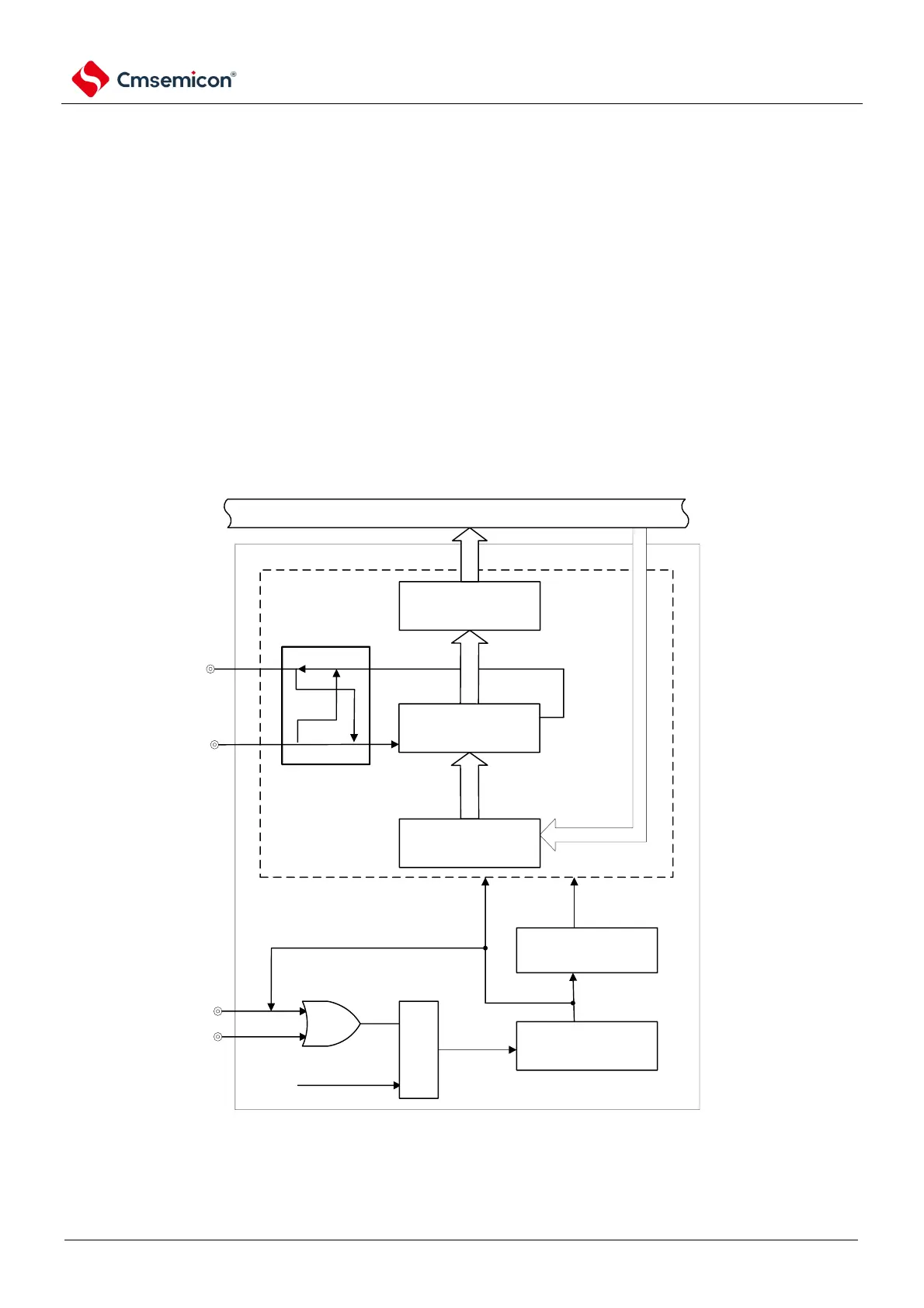
13.2 Structure of SPI
Figure13-1 Block diagram of serial interface SPI