CMS32L051 User Manual |Chapter 11 A/D Converter
www.mcu.com.cn 285 / 703
11.4.3 Software trigger mode (scan mode, continuous conversion mode)
(1) In the stop state, the ADCE bit of the mode register 0 (ADM0) of the A/D converter is 1 and enters
the A/D transition standby state.
(2) After counting the stable wait time (1 us) by software, the ADCS bit of the ADM0 register is 1 for the
register specified by the analog input channel (ADS The four analog input channels specified from
scan 0 to scan 3 are converted to A/D. A/D conversion is performed sequentially from the analog
input channels specified by Scan 0.
(3) A/D conversion of 4 analog input channels in succession. Whenever the A/D conversion ends, the
conversion results are saved to the A/D conversion result register (ADCR, ADCRH) and an A/D
conversion end interrupt request signal is generated (INTAD). Immediately after the A/D conversion
of the 4 channels is completed, the next A/D conversion (4 channels) is automatically started from
the set channel.
(4) If you override the 1 to the ADCS bit during the conversion, the current A/D conversion is aborted
immediately and the conversion begins again.
(5) If the ADS registers are overwritten or overwritten during the conversion, the current A/D conversion
is aborted immediately and then A/D converted from the original channel respecified by the ADS
registers.
(6) The A/D conversion does not start even if the input hardware triggers during the conversion.
(7) If the ADCS bit is 0 during the conversion, the current A/D conversion is aborted immediately and
then enters the A/D transition standby.
(8) If the ADCE bit is 0 in the A/D transition standby state, the A/D converter enters a stopped state.
When the ADCE bit is 0, even the ADCS set to 1 is ignored and the A/D conversion is not started.
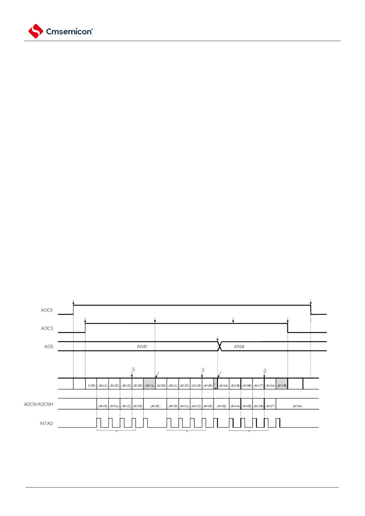
Figure11-18 Timing example of software trigger mode (scan mode, continuous conversion mode)
A/D conversion state
stop
converting
idle
conversion
start next cnversion
when A/D conversion
completes
auto restart conversion
when conversion
completes
auto restart conversion
when conversion
completes
conversion
idle
Stop
conversion
modify ADS (from ANI0 to ANI4)
during A/D conversion
clear ADCE bit to 0
clear ADCS bit to 0
during conversion
generate hardware trigger (be ignored)
during A/D conversion operation
rewrite ADCS bit to 1 during A/D
conversion operation
set ADCS bit to 1 during
conversion idle state
set 1 to ADCE bit
4 interrupts generated in 1 complete scan 4 interrupts generated in 1 complete scan 4 interrupts generated in 1 complete scan