CMS32L051 User Manual |Chapter 8 15-Bit Interval Timer
www.mcu.com.cn 248 / 703
8.3.3 15-bit interval timer control register (ITMC)
This is the register that sets the start and stop of operation of the 15-bit interval timer and the comparison
value.
The ITMC registers are set via 16-bit memory operation instructions.
After the reset signal is generated, the value of this register changes to 7FFFH.
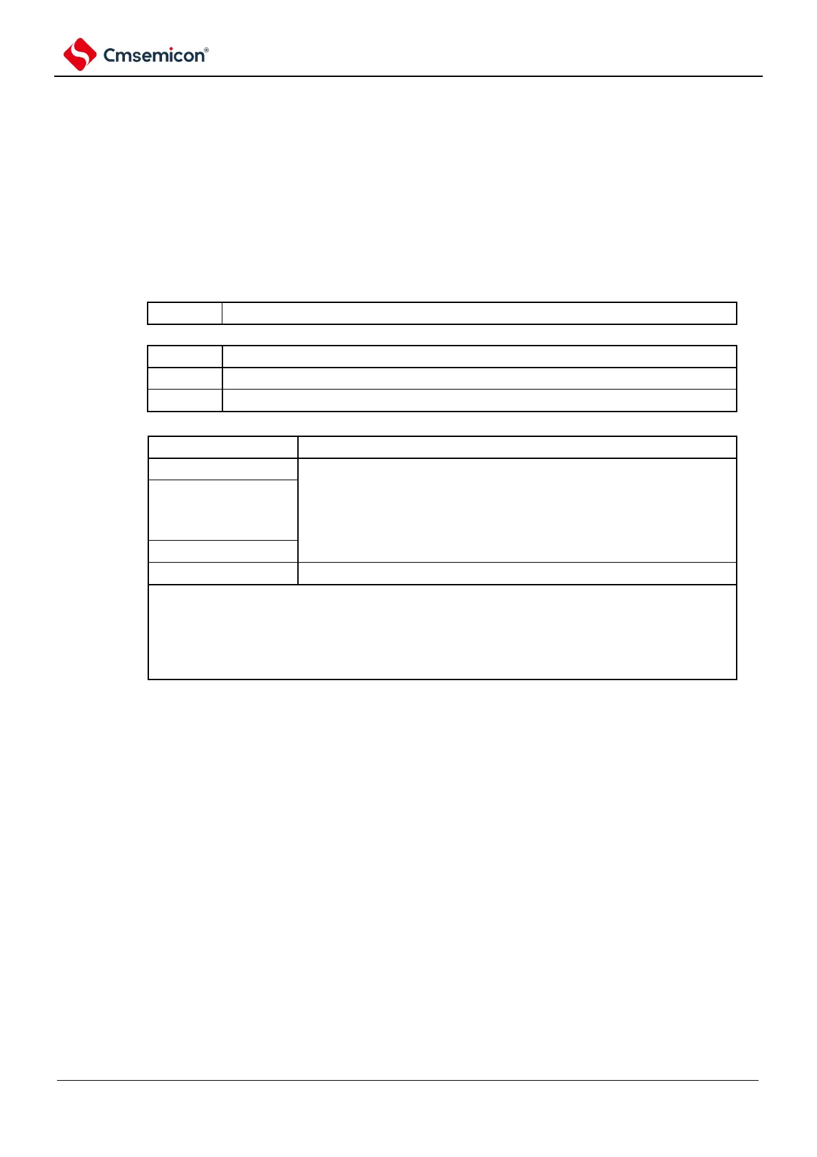
Figure 8-4 Format of 15-bit interval timer control register (ITMC)
Address: 0x40044F50 After reset: 7FFFHR/W
symbol
15 14~0
ITMC
15-bit interval timer operational control
Stop the run of the counter (clear the count).
Start the run of the counter.
15-bit interval timer comparison value setting
These bits produce a fixed-period interrupt of counting clock cycles
(ITCMP config value +1).
Example of an interrupt period when ITCMP1 4 to ITCMP0 is 0 001H or 7FFFH
~ ITCMP0=0001H, Count clock: f
SUB
=32.768kHz
1/32.768[kHz] ×(1+1)
ITCMP14~ITCMP0=7FFFH, Counting clock:
f
SUB
=32.768kHz1/32.768[kHz] ×(32767+1) =1000[ms]
Note:
1. To change the RINTE bit from 1 to 0, it must be overridden after setting INTIT to disable interrupt handling through
the interrupt mask flag register. To restart the run (change from 0 to 1), it must be set to allow interrupt processing
after clearing the ITIF flag.
2. The read value of the RINTE bit is reflected after 1 count clock after the RINTE bit is set.
3. After moving from sleep mode to normal operating mode, if you want to set the ITMC register and move to sleep mode
again, you must at least pass after confirming that the write value of the ITMC register is reflected or after setting the
ITMC register 1 count clock is then transferred to sleep mode.
4. Only change the setting of the ITCMP14 to ITCMP0 bits when RINTE = 0. However, it is possible to change the
settings of the ITCMP14 to ITCMP0 bits at the same time as when changing RINTE from 0 to 1 or 1 to 0.