CMS32L051 User Manual |Chapter 6 Function of EPWM Output Control Circuit
www.mcu.com.cn 218 / 703
6.5.2 Control method
The stepper motor is rotated, reversed or stopped in two-phase excitation mode by using eight EPWMOs.
Control the rotation speed via Timer's PWM mode.
In this example, Timer's CH0 and CH1 are used for the control of stepper motor 1, CH2 and CH3 are
used for the control of stepper motor 2. If you combine 2 Timer channels, you can generate pulses of any
period and duty cycle. CH0 and CH2 are the main control channels and operate as interval timer mode. CH1
and CH3 are slave channels and operate as single-count mode.
In addition, the cross-current prevention time (no overlapping time) is inserted when switching the output
type.
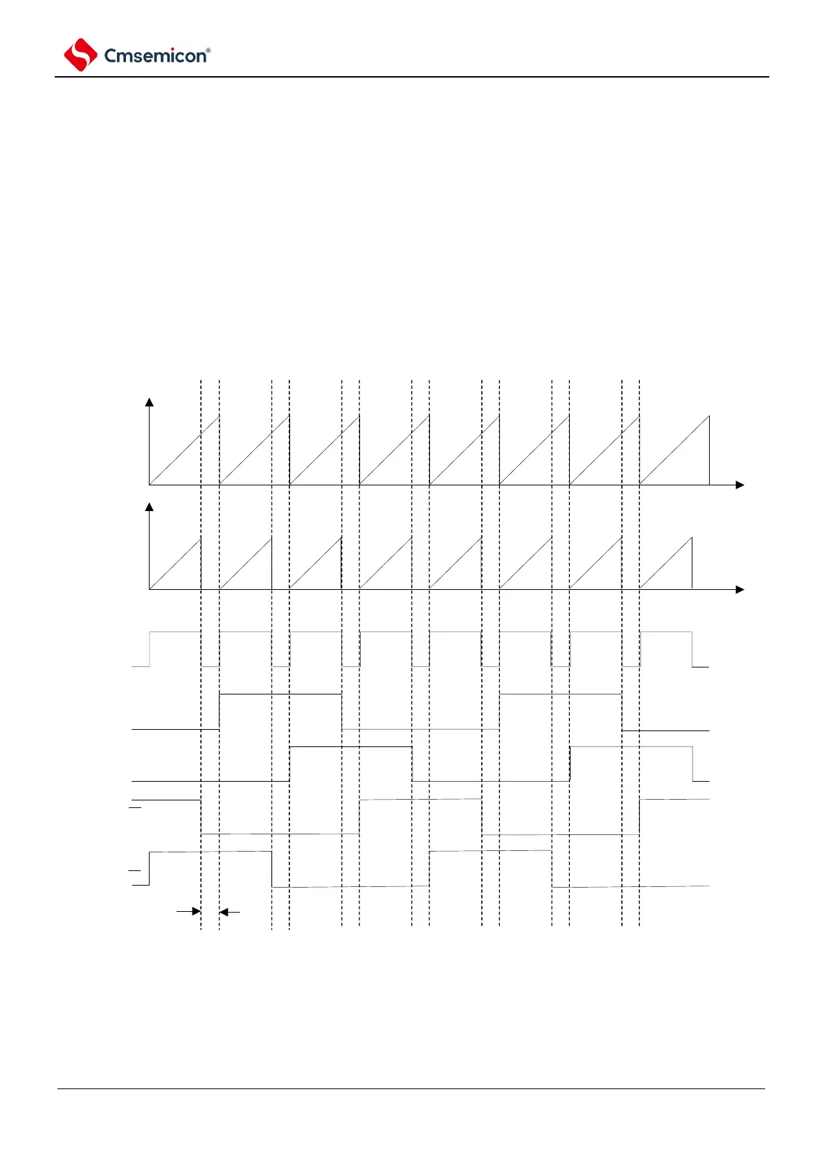
An example of a waveform for stepper motor control is shown in Figure 6-13.
Figure 6-13 Waveform example of step motor control