CMS32L051 User Manual |Chapter 15 IrDA
www.mcu.com.cn 569 / 703
15.2 Registers for controlling the IrDA
Control the IrDA function through the following registers.
Peripheral enable register 0 (PER0).
•
IrDA control register (IRCR).
15.2.1 Peripheral enable register 0 (PER0)
The PER0 register is a register that sets the clock to be enable or disable to be supplied to each
peripheral hardware. Reduce power consumption and noise by stopping clocking unused hardware.
To use IrDA, you must set bit6 (IRDAEN) to 1.
The PER0 register is set via an 8-bit memory operation command.
After the reset signal is generated, the value of this register becomes 00H.
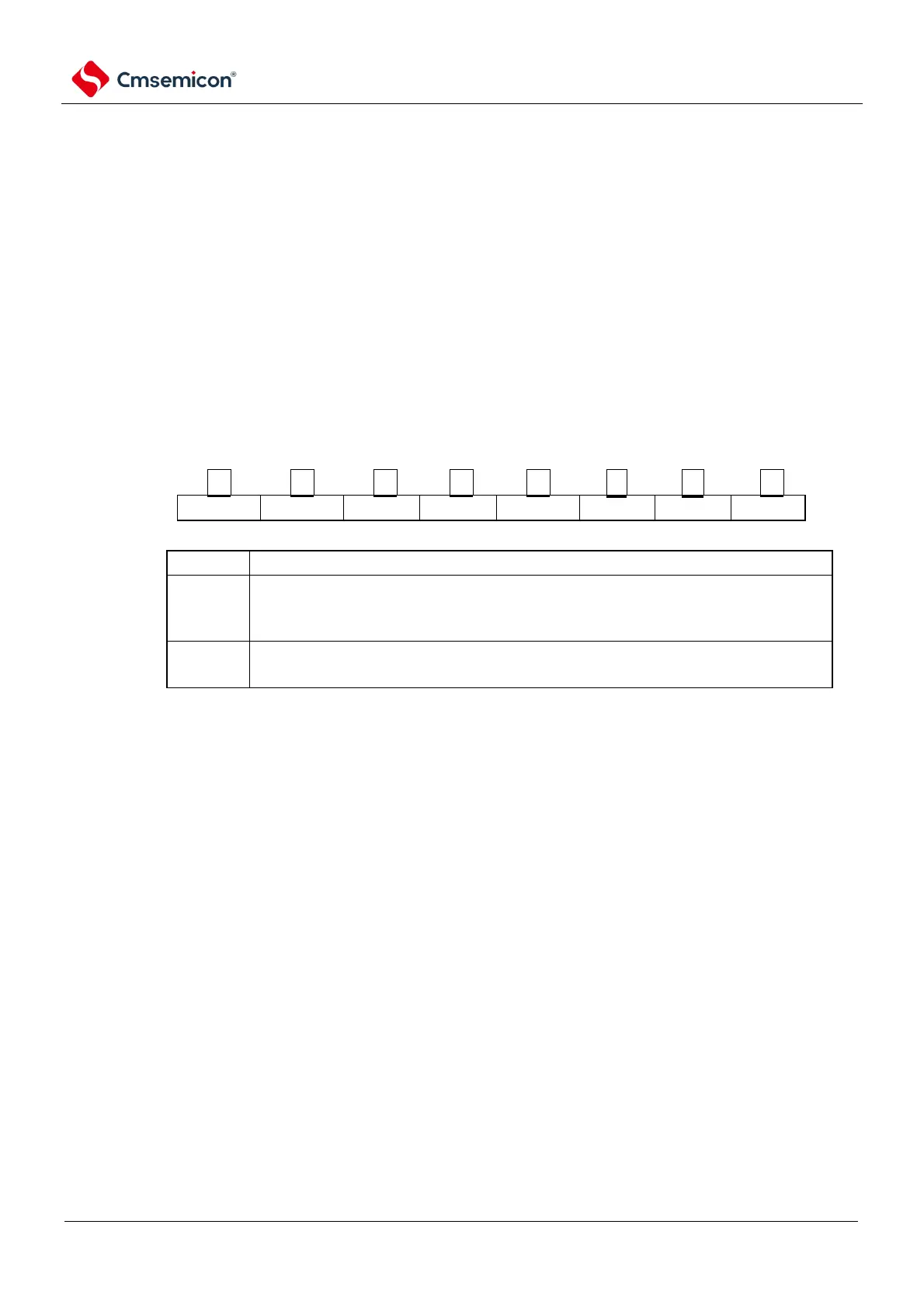
Figure 15-2 Peripheral enable register 0 (PER0)
Address: 40020 420H After reset: 00HR/W
symbol
PER0
Note 1 When setting the IrDA, the IRDAEN bit must be set to "1" first. When the IRDAEN bit is "0", the write operation of
the IrDA control register is ignored, and the read value is all initial.