CMS32L051 User Manual |Chapter 12 Universal Serial Communication Unit
www.mcu.com.cn 307 / 703
12.3.3 Serial mode register mn (SMRmn)
The SMRmn register is a register that sets the channel n operating mode, selects the operating clock (f
MCK
), specifies whether the serial clock (f
SCLK
) input can be used, sets the start trigger, and operates the mode
(SSPI, UART, Simplified I
2
C) settings and interrupt source selection. In addition, the inverting level of the
received data is set only in UART mode.
Overwriting the SMRmn register during operation (SEmn=1) is prohibited, but the MDmn0 bit can be
overridden during operation.
The SMRmn register is set via a 16-bit memory operation command.
After the reset signal is generated, the value of the SMRmn register changes to 0020H.
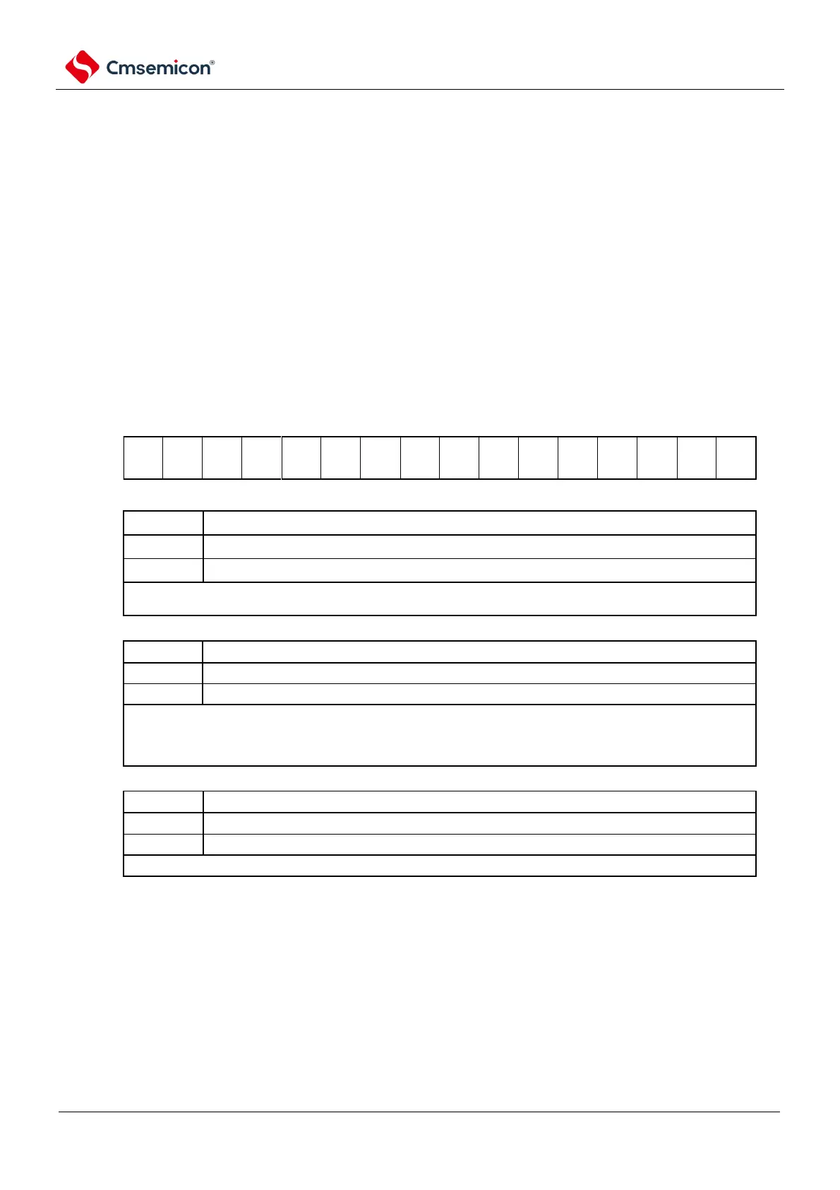
Figure 12-7 Format of serial mode register mn (SMRmn) (1/2)
Address: 40041110H(SMR00)~40041116H(SMR03) After reset: 0020HR/W
40041550H(SMR10)~40041552H(SMR11)
Symbol
15 14 13 12 11 10 9 8 7 6 5 4 3 2 1 0
SMRmn
Selection of channel n operating clock (f
MCK
)
The SPSm register sets the operating clock CKm0
The SPSm register sets the operating clock CKm1
The operating clock (f
MCK
) is used for edge detection circuitry. The transmit clock (f
TCLK)
is generated by setting
the CCSmn bit and the SDRmn register high 7 bits.
Selection of channel n transmit clock (f
TCLK
)
The CKSmn bit specifies the crossover clock of the running clock f
MCK
The input clock f
SCLK
from the SCLKp pin (slave transfer in SSPI mode).
The transmit clock f
TCLK
is used for shift registers, communication control circuits, output controllers, interrupt
control circuits, and error control circuits. When the CCSmn bit is 0, the runtime clock (f
MCK
) is divided by the
high 7 bits of the SDRmn register.
Selection of start triggering sources
Only software triggers are valid (selected in SSPI, UART Send, Simplified I2C).
The effective edge of the RxDq pin (selected when received by the UART).
Transmission begins when the above conditions are met after setting the SSm register to 1.
Note 1 SMR01, SMR03, SMR11 registers only.
Note You must set bit13~9, 7, 4, 3 (SMR00, SMR02, SMR10 registers are bit13~6, 4, 3) to 0, and set bit5 to 1.
Remark m: Unit number (m=0, 1) n: channel number (n=0~3) p: SSPI number (p=00, 01, 10, 11, 20, 21)
q: UART number (q=0~2) r: IIC number (r=00, 01, 10, 11, 20, 21)