CMS32L051 User Manual |Chapter 15 IrDA
www.mcu.com.cn 572 / 703
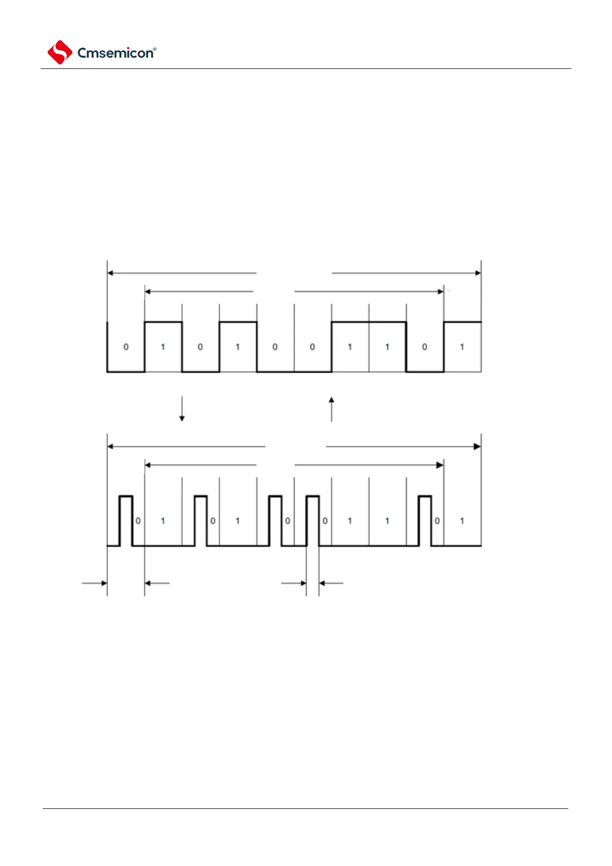
15.3.2 Transmission
At the time of transmission, the output signal (UART frame) from the SCI is converted to an IR frame via
IrDA (see Figure 15-4).
At IRTXINV bit 0 and serial data is 0, the output bit period (1-bit width period) x 3/16 high level pulse
(initial value). In addition, the high pulse width can be changed according to the setting value of IRCKS2 to
IRCKS0 bits. As standard, a minimum pulse width of 1.41 u s for high levels is specified for a maximum of
(3/16+2.5%) x bit period, or (3/16 x bit period) of +0.6 us.
When the CPU or peripheral hardware clock (fCLK) is 24MHz, the minimum high pulse width that can be
set is 1.5 u s (the condition that the high-level pulse width specified above is not less than 1.41us is satisfied).
In addition, when the serial data is 1, no pulse is output.
Figure 15-4 Transmit/receive operation diagram of IrDA
UART frame
transmit
IR frame
Start
bit
Start
bit
data
data
Stop
bit
Stop
bit
reception
bit
period
min pulse bit width 1.41us
max pulse width as bit period
x(3/16+2.5%)or(3/16 xbit period)+0.6us
15.3.3 Reception
When received, the data of the IR frame is converted to a UART frame via IrDA and then entered into the
SCI. When the IRRXINV bit is 0 and a high pulse is detected, low data is output. If there is no pulse within the
1-bit period, high level data is output. Care must be taken that pulses smaller than the minimum pulse width of
1.41us cannot be recognized.