CMS32L051 User Manual |Chapter 7 Real-Time Clock
www.mcu.com.cn 225 / 703
7.3.3 Real-time clock control register0 (RTCC0)
This is an 8-bit register that sets the start or stop of operation of the real-time clock, control of the
RTC1HZ pin, 12/24-hour system, and fixed-cycle interrupt function.
The RTCC0 register is set via an 8-bit memory operation command. After the reset signal is generated, the
value of this register becomes 00H.
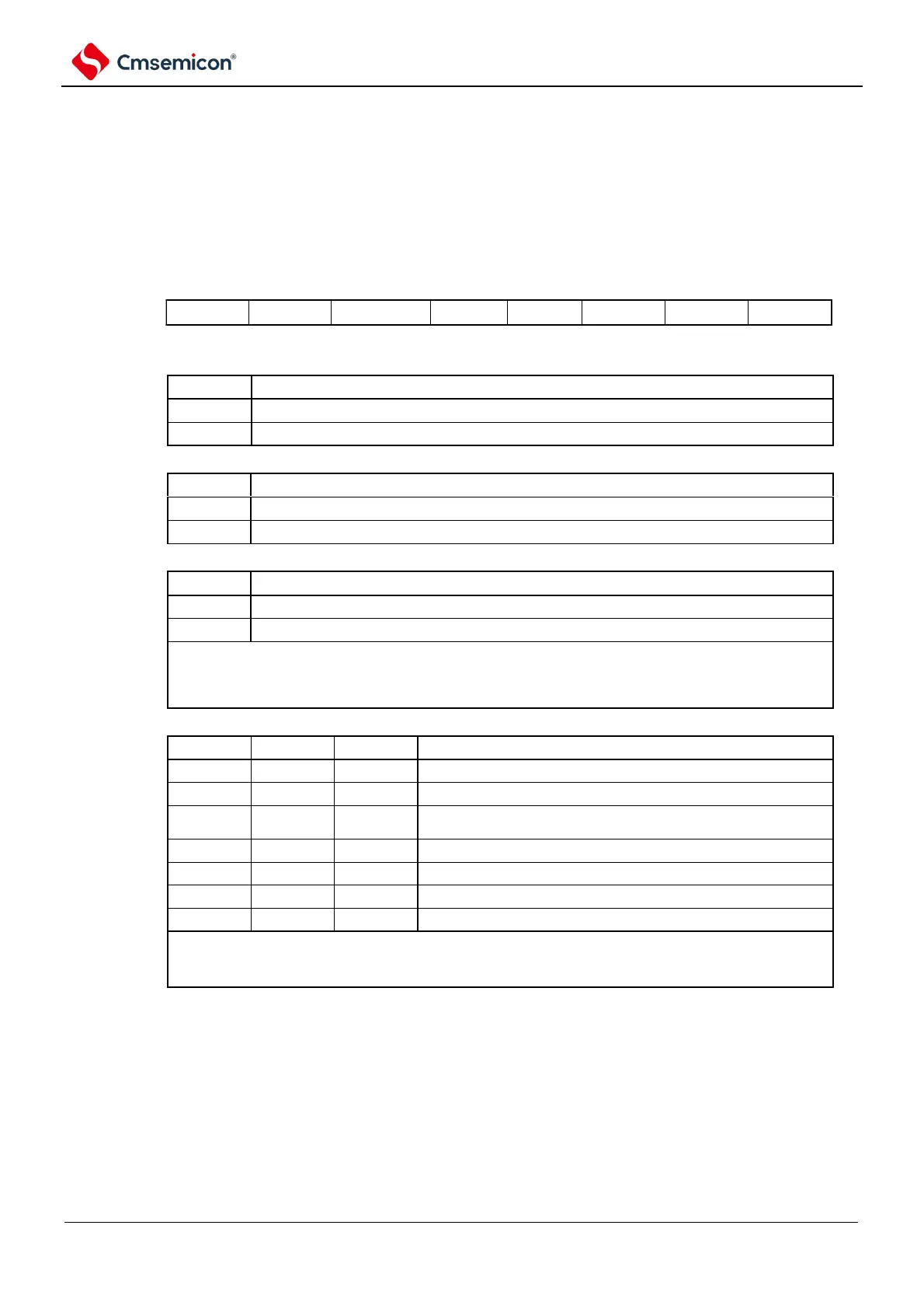
Figure 7-4 Format of real-time clock control register 0 (RTCC0)
Address: 0x40044F5D After reset: 00H R/W
symbol
RTCC0
Operational control of real-time clock
Stop the operation of the counter.
Start the operation of the counter.
Output control of RTC1HZ pin
Disable the output of the RTC1HZ pin (1Hz).
Enable the output of the RTC1HZ pin (1Hz).
Selection of 12-hour system/24-hour system
12-hour system (for morning or afternoon).
the value of the AMPM bit, the RWAIT bit (bit0 of the real-time clock control register 1
(RTCC1)) must be set to 1 and rewrite later. If you change the value of the AMPM bit, the value of the
hour count register (HOUR) becomes the corresponding value of the time system in which you set it.
-2.
Selection of fixed period interruption (INTRTC)
Do not use the fixed-cycle interrupt feature.
0.5 seconds once (synchronized with second accumulation).
Once every 1 second (at the same time as the second
accumulation).
Once every 1 minute (00 seconds per minute).
Once every 1 hour (00 minutes and 00 seconds per hour).
Once a day (00:00:00 every day).
Once every 1 month (1 of each month at 00:00:00 AM).
To change the value of the CT2~CT0 bits while the counter is running (RTCE=1), it must be overridden
after setting the INTRTC to disable interrupt handling through the interrupt mask flag register, and the RIFG
must be cleared after the override flags and RTCIF flags, and then set to allow interrupt handling.
Note 1 When the RCE bit is 1, the RCLOE1 bit cannot be changed.
2. When the RTCE bit is 0, even if the RCLOE1 set to 1 is not output 1Hz.
Remark ×: Ignore