CMS32L051 User Manual |Chapter 6 Function of EPWM Output Control Circuit
www.mcu.com.cn 214 / 703
6.4 Control example of brushless DC motor
The following is an example of using the EPWM control function to control a brushless DC motor
(hereinafter referred to as a BLDC motor).
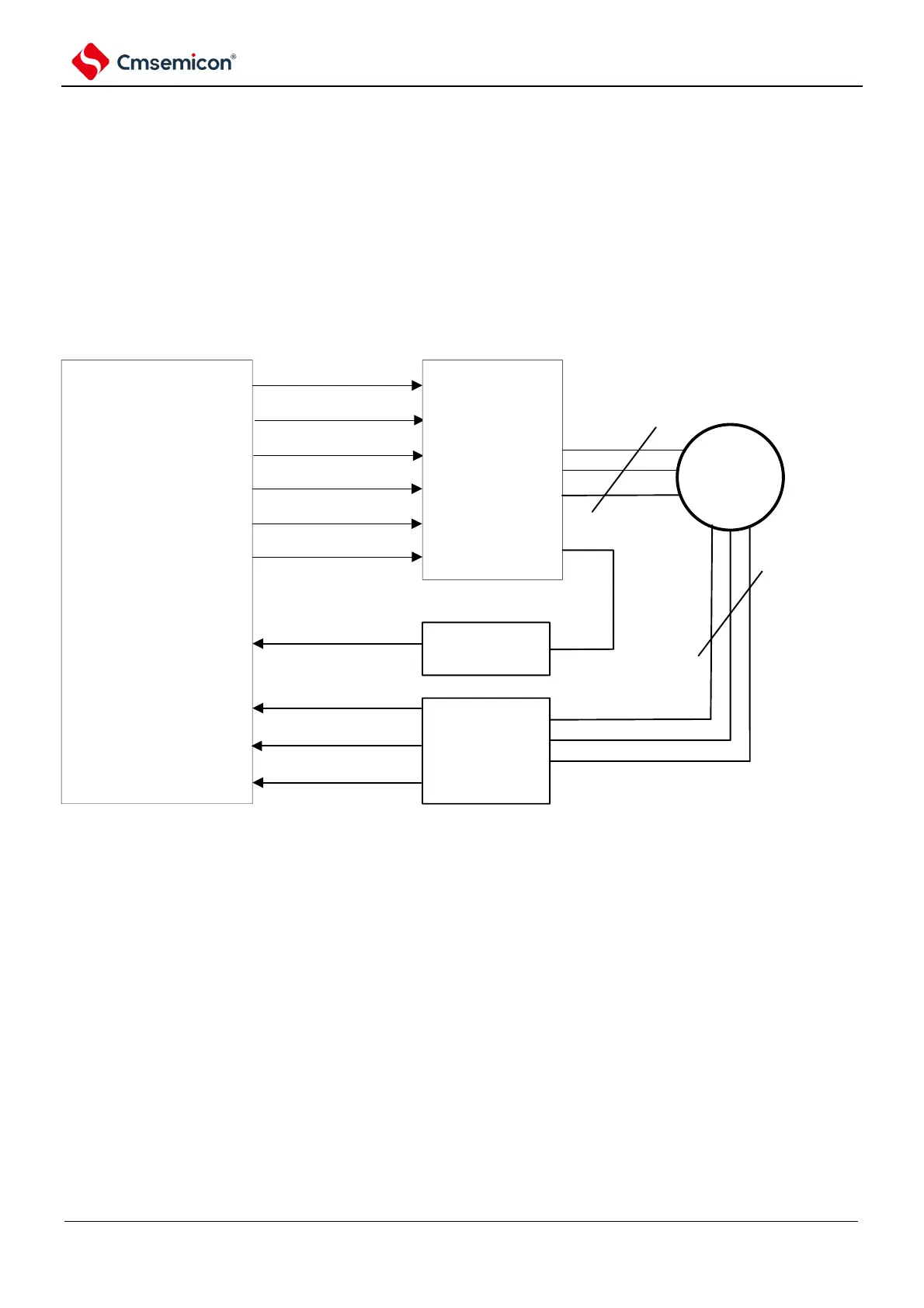
6.4.1 Example of a hardware connection
An example of a hardware connection for a brushless DC motor is shown in Figure 6-10. In this
example, EPWMO00~EPWMO05 (output) is used for output control of BLDC motors,
INTP1~INTP3(input) for the output signal of the Hall sensor, and INTP0 (input) is used to force a
truncated signal.
Figure 6-10 Example of hardware connections