CMS32L051 User Manual |Chapter 12 Universal Serial Communication Unit
www.mcu.com.cn 422 / 703
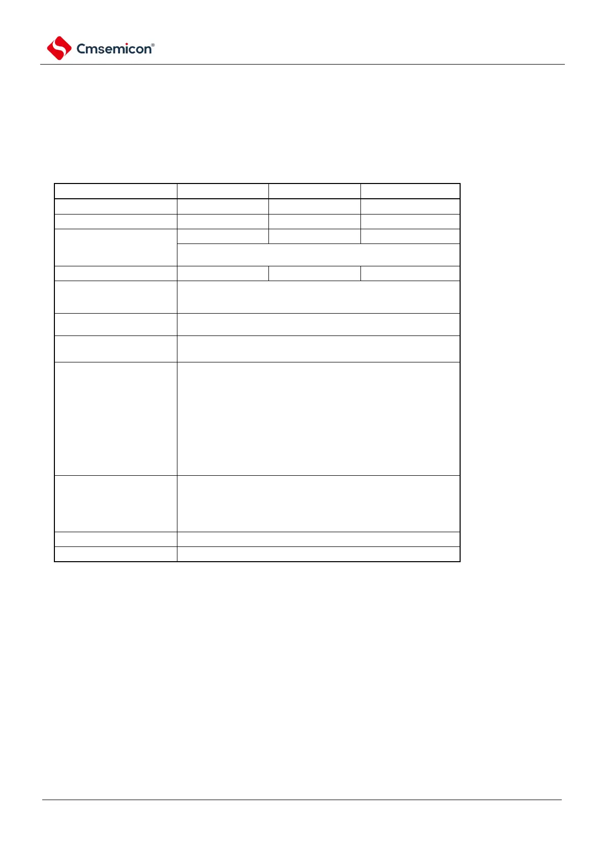
12.7.2 UART reception
UART reception is the operation of other devices of this product's microcontroller to receive data
asynchronously.
An odd number of the 2 channels used by the UART are used for UART reception. However, the SMR
registers for both odd and even channels need to be set.
Limited to end-of-transfer interrupts (disable setting buffer null
interrupts).
Detection Flag (PEFmn).
The length of the transmitted
data
7-bit, 8-bit or 9-digit
Note
1
Max.f
MCK
/6[bps](),
Min.f
CLK
/(2×2
15
×128)[bps]
Normal-
phase
output
(default:
high).
Inverting
output
(default:
low).
You can choose from the following:
(no parity).
Appending zero check (no parity).
-check
Note 1 Only UART0 supports 9-bit data length.
2. Must be used within the scope of the peripheral functional characteristics that meet this condition and meet the
electrical characteristics (refer to the data sheet).
Note 1. f
MCK
: The operating clock frequency of the object channel
f
CLK
: System clock frequency
2.m: Unit number (m=0, 1) n: channel number (n=1, 3) mn=01, 03, 11.