CMS32L051 User Manual |Chapter 5 Universal Timer Unit (Timer4)
www.mcu.com.cn 132 / 703
5.3.7 Timer channel stop register m (TTm)
The TTm register is the trigger register that sets the count stop for each channel.
If each position is 1, the timer channel allows the corresponding bit of the status register m (TEm) to
be cleared 0. Because the TTmn bit, TTHm1 bit, and TTHm3 bit are the trigger bits, if they become run
stop states (TEmn, TEHm1, TEHm3=0), the TTmn bit, the TTHm1 bit, and the TTHm3 bit are immediately
cleared.
The TTm register is set via a 16-bit memory operation command.
The low 8 bits of the TTm register can be set with TTmL and via 8-bit memory operation instructions.
After the reset signal is generated, the value of the TTm register changes to 0000H.
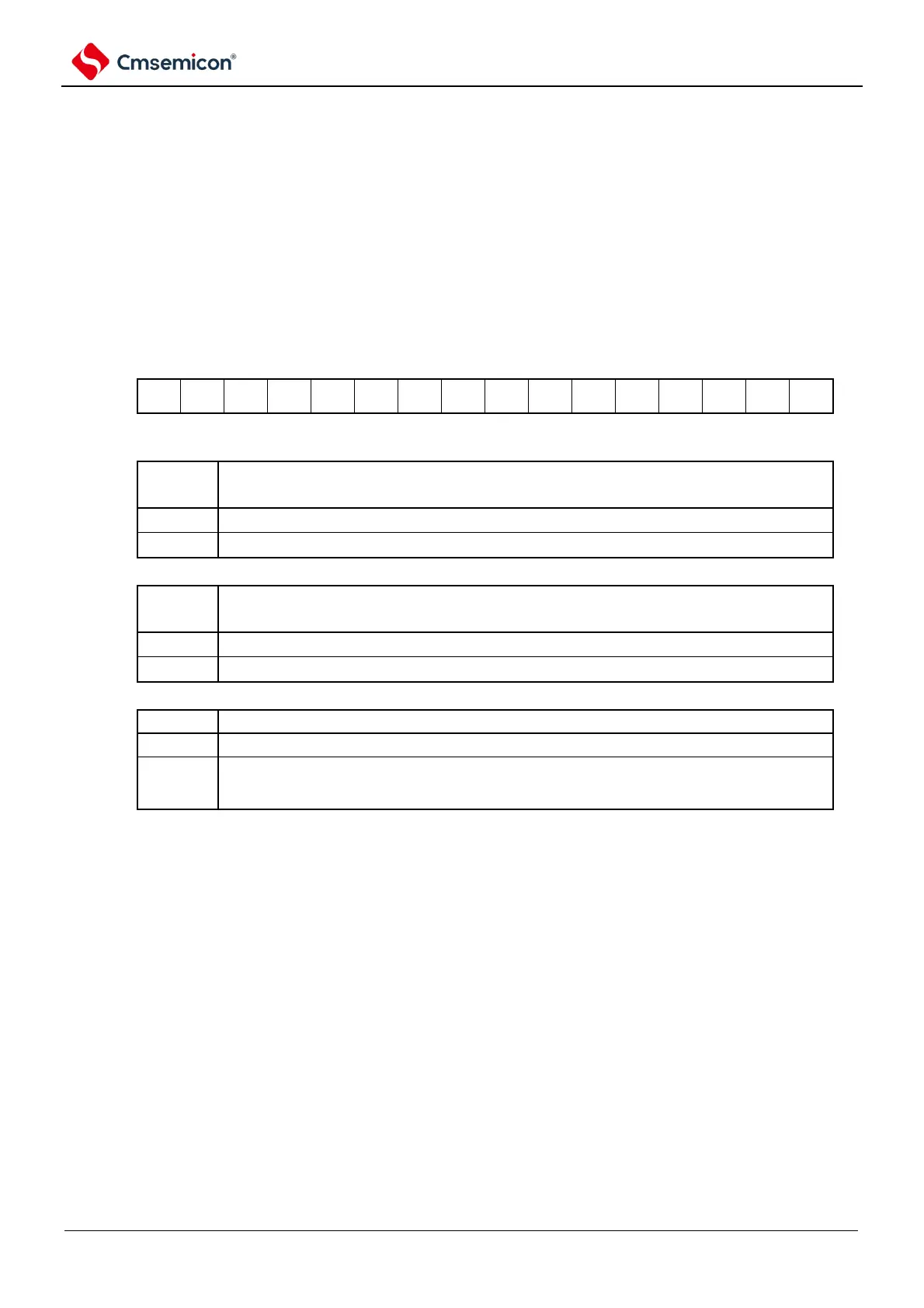
Figure 5-16 Table of Timer Channel Stop Register m (TTm)
Symbol
15 14 13 12 11 10 9 8 7 6 5 4 3 2 1 0
TTm
Clear the TEmn bit to 0 and enter the count stop state.
When channels 1 and 3 are in 8-bit timer mode, TTm1 and TTm3 are the operation stop triggers
for the low 8-bit timer.
Note You must set bit15~12, 10, 8~4 to 0.
Note: 1. The read value of the TTm register is always 0.
2. m: unit number (m=0,1) n: channel number (n=0~3).