CMS32L051 User Manual |Chapter 5 Universal Timer Unit (Timer4)
www.mcu.com.cn 110 / 703
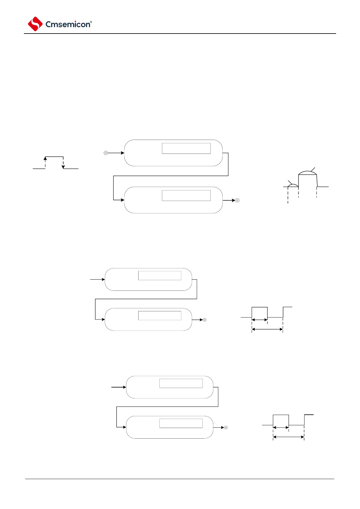
5.1.2 Multi-channel linkage operation function
The multi-channel linkage operation function is a combination of the master channel (the reference timer
for the main control period) and the slave channel (the timer that operates in accordance with the master
channel).
The multi-channel linkage operation function can be used as the following mode.
(1) Single trigger pulse output
Use 2 channels in pairs to generate a single-trigger pulse that arbitrarily sets the output timing and pulse
width.
Comparision
operation
edge detection
channel n
(master control)
timer input
(TImn)
Comparision
operation
Channel P
(Slave)
start
(master control)
set
(master control)
reset
(Slave)
pulse
width
output timing
sequence
timer output
(TOmp)
interrupt
singnal
(INTTmn)
(2)
PWM (Pulse Width Modulation) output
Use 2 channels in pairs to generate pulses that can set the period and duty cycle arbitrarily.
Comparision
operation
channel N
(master control)
Action clock
Comparision
operation
channel P
(slave)
timer output
(TOmp)
duty cycle
period
interrupt
singnal
(INTTmn)
(3)
Multiple PWM (Pulse Width Modulation) outputs
Up to 3 arbitrary duty cycle PWM signals can be generated in a fixed period by extending the PWM
function and using 1 master channel and multiple slave channels.
Comparision
operation
channel N
(master control)
Action clock
Comparision
operation
channel P
(slave)
timer output
(TOmp)
duty cycle
period
interrupt
singnal
(INTTmn)
Note For more information about the multi-channel linkage operation function rules, please refer to it 5.4.1 Basic rules of
the multi-channel linkage operation function
Remark m: Unit number (m=0,1) n: Channel number (n=0 ~ 3) p, q: The slave channel number(n< p< )