CMS32L051 User Manual |Chapter 14 Serial interface IICA
www.mcu.com.cn 495 / 703
14.3.5 IICA control register n1 (IICCTLn1)
This is a register used to set the I
2
C operating mode and detect the status of the SCLAn pin and the
SDAAn pin.
The IICCTLn1 register is set via an 8-bit memory operation command. However, only CLDn bits and
DADn bits can be read.
In addition to the WUPn bit, bit7 must be disabled for I
2
C to operate (IICA control register n0 (IICCTLn0).
(IICEn)=0) when setting the IICCTLn1 register.
After the reset signal is generated, the value of this register becomes 00H.
Figure 14-9 Format of IICA control register n1 (IICCTLn1) (1/2)
Address: 0x40041A31 After reset: 00HR/W
Note
1
symbol
IICCTLn1
Address matching control of wake-up
In deep sleep mode, stop the operation of the address matching wake-up function.
In deep sleep mode, address matching is allowed to operate for wake-up functions.
To transfer to deep sleep mode by setting the WUPn bit to "1", at least three F
MCK
clocks must pass after
setting the WUPn bit to "1", and then the deep sleep instruction must be executed (refer to "Figure 14-28
Flow when setting the WUPn bit to "1"). The WUPn bit must be cleared to "0" after the address is matched
or the extension code is received. It is possible to participate in subsequent communication by clearing
the WUPn bit to "0" (it is necessary to release the wait and write send data after clearing the WUPn bit to
"0").
In the state of WUPn bit "1", the interrupt timing when the address is matched or the extension code is
received is the same as the interrupt timing when WUPn bit is "0".
(The delay difference of sampling error is generated according to the clock). In addition, when the WUPn
bit is "1", even if the SPIEn bit is set to "1", no stop condition interrupt is generated.
Clear condition (WUPn=0).
the extension code is received).
Set by instruction (MSTSn=0, EXCn=0, COIn=0,
and STDn=0 (do not participate in
communication))
Note 2
.
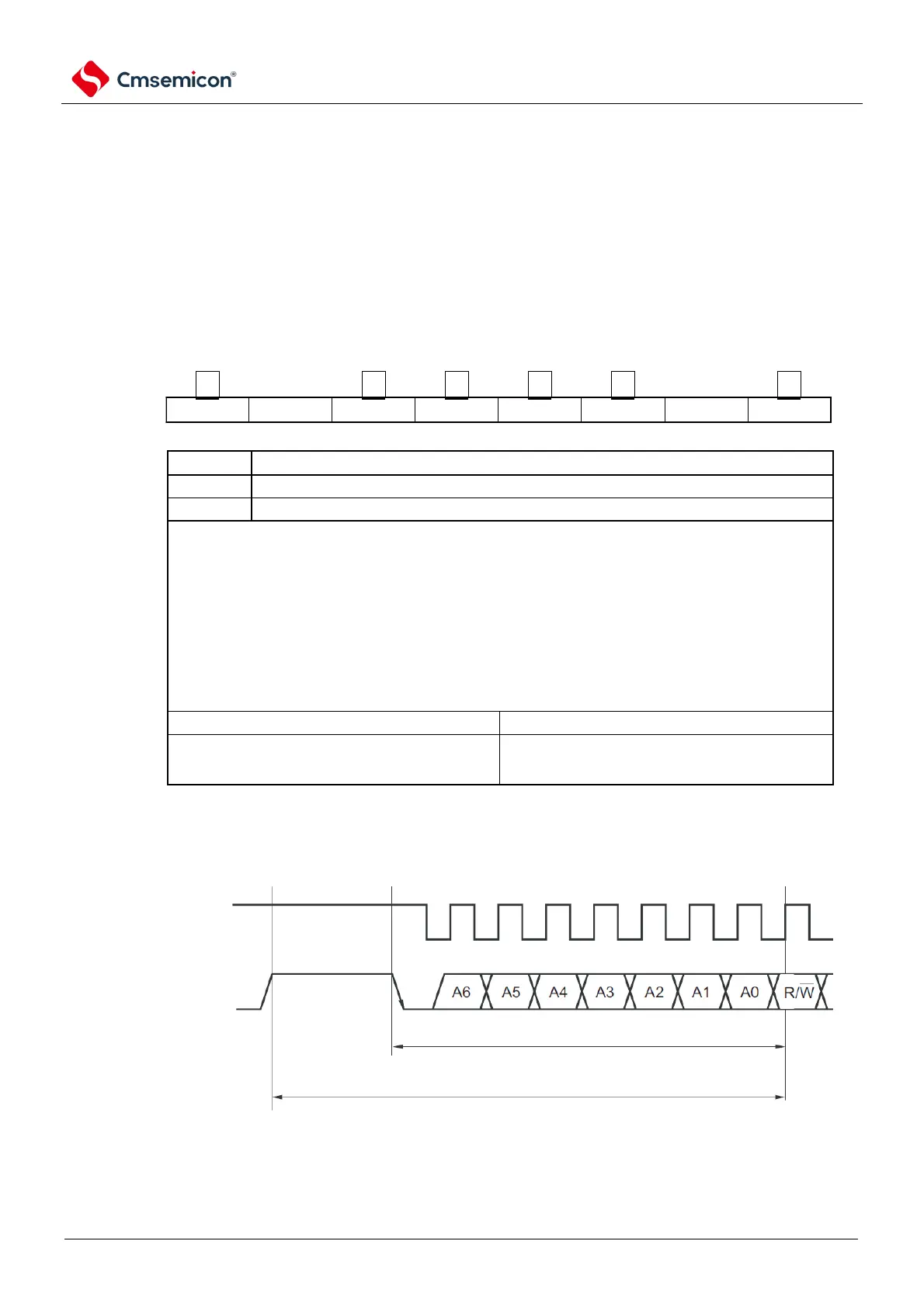
Note 1. Bit4 and bit5 are read-only bits.
2. During the period shown below, it is necessary to confirm the status of the IICA status register n (IICSn) and set it up.
SCLAn
SDAAn
during this period, confirm operation state via IICSn and set WUP bit.
max duration from reading IICSn till set
WUPn bit