CMS32L051 User Manual |Chapter 4 Clock Generation Circuit
www.mcu.com.cn 80 / 703
4.4 System clock oscillation circuit
4.4.1 X1 oscillation circuit
The X1 oscillation circuit is oscillated by a crystal resonator or ceramic resonator (1 to 20 MHz)
connected to the X1 and X2 pins. An external clock can also be input, in which case the clock signal must
be input to the EXCLK pin.
When using the X1 oscillation circuit, the following settings must be made to bit 7 and bit 6 (EXCLK,
OSCSEL) of the Clock Operation Mode Control Register (CMC):
Crystal or ceramic oscillation: EXCLK, OSCSEL = 0, 1
External clock inputs: EXCLK, OSCSEL=1, 1
When the X1 oscillation circuit is not used, it must be set to port mode (EXCLK, OSCSEL=0, 0). Also,
when it is not used as an input and output port, please refer to Table 2-3 for the handling of each unused
pin.
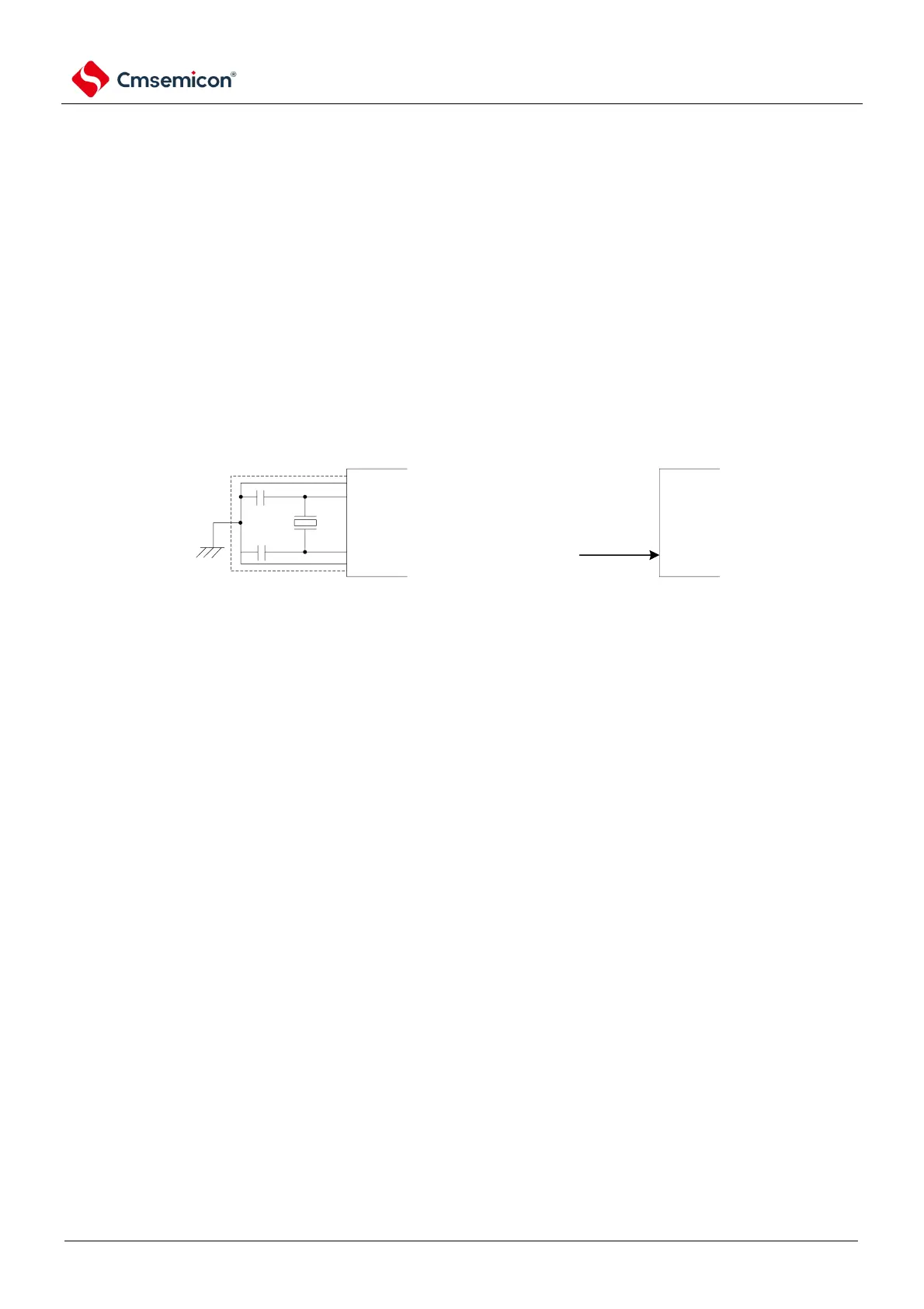
An example of an external circuit for an X1 oscillation circuit is shown in Figure 4-13.
Figure 4-13 Example of an external circuit for the X1 oscillation circuit
Vss
X1
X2
Crystal oscilator or ceramic oscillator
(a) Crystal or ceramic oscillator
(b) External clock
EXCLKExternal clock
Considerations are shown on the following page.
4.4.2 XT1 oscillation circuit
The XT1 oscillation circuit is via a crystal resonator (32.768kHz (TYP.)) connected to the XT1 pin
and the XT2 pin to oscillate. When using the XT1 oscillation circuit, bit4 (OSCSELS) of the clock mode
control register (CMC) must be set to 1 to also input an external clock, which must be given the
EXCLKS pin input clock signal.
When using the XT1 oscillation circuit, bit5 and bit4 (EXCLKS, OSCSELS) of the clock operation
mode control register (CMC) must be controlled) to make the following settings:
•
Crystal oscillation: EXCLKS, OSCSELS=0, 1
•
External clock inputs: EXCLKS, OSCSELS=1, 1
When the XT1 oscillation circuit is not used, it must be set to port mode (EXCLKS, OSCSELS=0,
0). Also, when it is not used as an input and output port, please refer to Table 2-3 Handling of Unused
Pins. An example of an external circuit for an XT1 oscillation circuit is shown in Figure 4-14.