CMS32L051 User Manual |Chapter 4 Clock Generation Circuit
www.mcu.com.cn 71 / 703
4.3.5 Oscillation stabilization time selection register (OSTS)
This is the register that selects the oscillation settling time of the X1 clock.
If the X1 clock is oscillated, it automatically waits for the time the OSTS register is set after the X1
oscillation circuit runs (MSTOP=0).
If you switch the CPU clock from the high-speed internal oscillator clock or the subsystem clock to the X1
clock, or if the CPU clock is a high-speed internal oscillator clock and is decommissioned after transferring to
deep sleep mode while the X1 clock oscillates, the oscillation settling time must be confirmed by the oscillation
settling time counter's status register (OSTC).
The time set by the OSTS register can be confirmed through the OSTC register.
Set the OSTS registers via 8-bit memory operation instructions. After the reset signal is generated, the
value of this register changes to 07H.
Figure 4-6 Format of oscillation stabilization time selection register (OSTS)
Address: 40020403H After reset: 07H R/W
Symbol
7 6 5 4 3 2 1 0
OSTS
Note 1 To change the settings of the OSTS register, you must change it before placing the MSTOP position of the clock
running state control register (CSC) 0.
2. The oscillation settling time counter only counts during the oscillation stabilization time set by the OSTS register.
In the following cases, the oscillation settling time of the OSTS register must be set to be greater than the count
value confirmed by the OSTC register after the oscillation has begun.
-speed internal oscillator clock or a subsystem clock and oscillation of the X1
clock is to begin
-speed internal oscillator clock and deep sleep mode is removed after moving to
deep sleep mode in the state of X1 clock oscillation (so it must be noted that the OSTS register after deep sleep
mode is dismissed, only OSTS is set.) The state of the oscillation set by the register within the stable time).
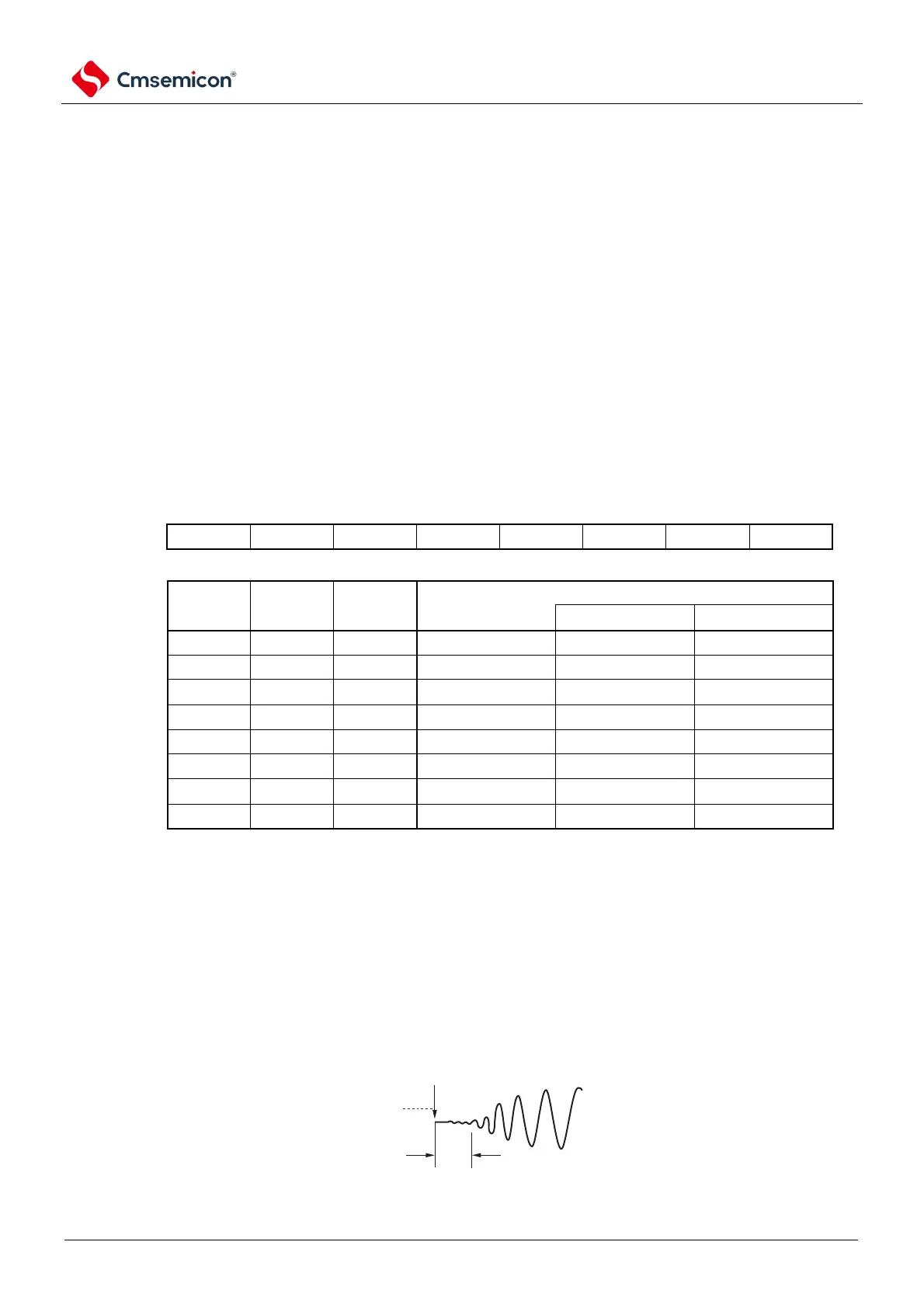
3.The oscillation stabilization time of the X1 clock does not include the time before the clock starts oscillating
(Figure a below).
Deep sleep mode is released
X1 pin
Voltage waveform
a
Note f
X
: X1 clock oscillation frequency