CMS32L051 User Manual |Chapter 6 Function of EPWM Output Control Circuit
www.mcu.com.cn 207 / 703
6.2.1 Peripheral enable register 1 (PER1).
The PER1 register is a register that sets the clock that allows or disables clocking each peripheral
hardware.
Reduce power consumption and noise by stopping clocking unused hardware.
To use the EPWM function, EPWMEN must be set to 1.
See 4.3.6 Peripheral Permissible Registers 0, 1 (PER0, PER1) for details
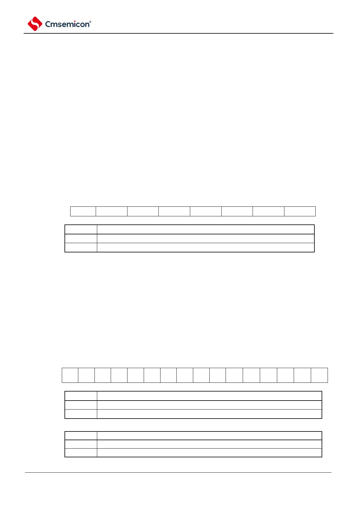
6.2.2 EPWM input source selection register (EPWMSRC)
The EPWMSRC register selects the source clock of the input clock of the real-time output circuit. Select
Timer's timer output TO01 or TO03 as the source clock and input to the EPWM.
The EPWMSRC register is set via an 8-bit memory operation command.
By generating a reset signal, the value of this register becomes 00H.
Figure 6-2 Format of EPWM input source selection register
Note n: Channel number (n=0~7).
6.2.3 EPWM output control register (EPWMCTL)
The EPWMCTL register performs allowable control and reverse control of the waveform output of
EPWMO00 to EPWMO03.
The EPWMCTL registers are set via 16-bit memory operation instructions.
After the reset signal is generated, the value of this register becomes 00H.
Figure 6-3 Format of EPWM Output Control Register (EPWMCTL).