CMS32L051 User Manual |Chapter 14 Serial interface IICA
www.mcu.com.cn 501 / 703
14.5 Definition and control method of I
2
C-bus
The following describes the serial data communication format and signals used by the I
2
C-bus.
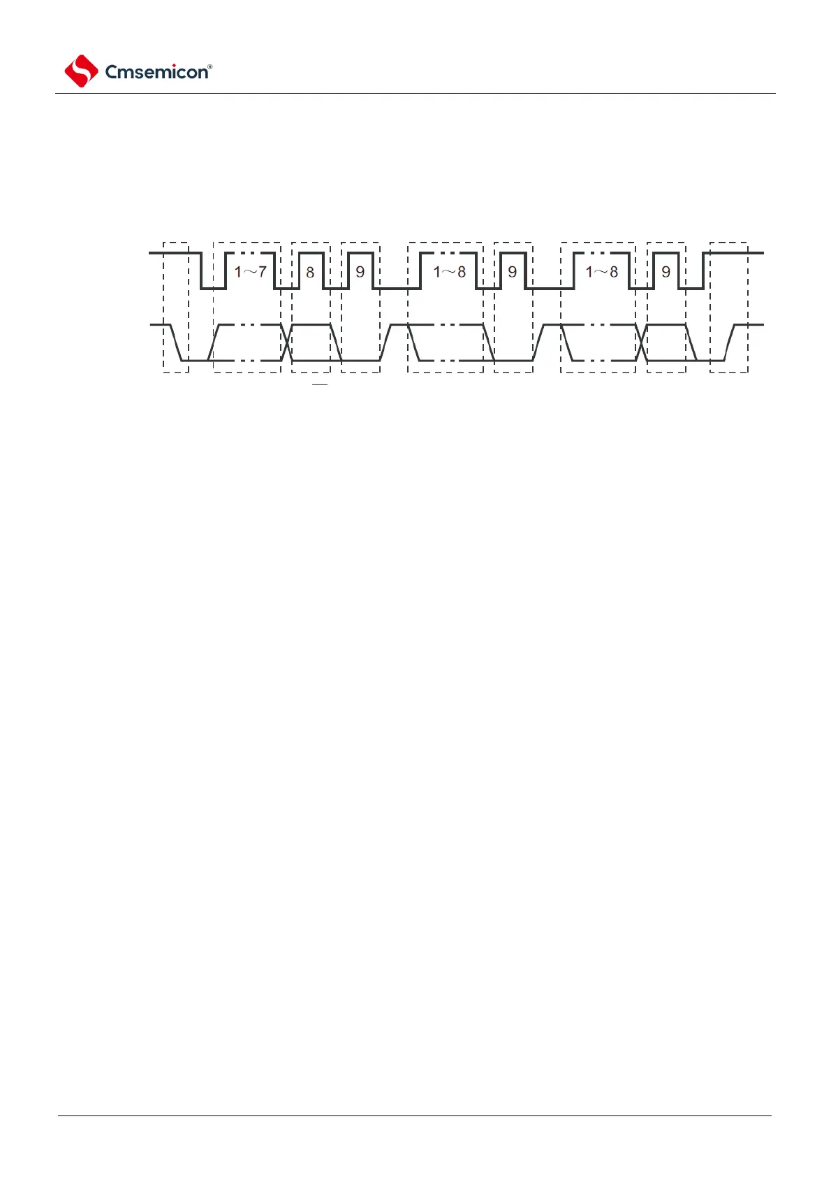
Each transmission timing of "start condition", "address", "data" and "stop condition" generated on the serial
data bus of the I
2
C bus is shown in the figure below.
Figure 14-13 Serial data transfer timing for the I2C bus
The master device generates start conditions, slave addresses, and stop conditions.
Both the master and slave devices generate a response (ACK) (in general, the receiver outputs 8 bits of
data). The master device continuously outputs the serial clock (SCLAn). However, the slave can extend the
low level of the SCLAn pin and plug in the wait.