CMS32L051 User Manual |Chapter 6 Function of EPWM Output Control Circuit
www.mcu.com.cn 212 / 703
6.3.2 Normal operation
Depending on the register settings, four output data can be selected, namely forward waveform output,
inverted waveform output, low level output, and high-level output. The EPWMCTL registers can be changed
at runtime. Both OE0n bits and IE0n bits must be written at the same time.
For details, please refer to Table 6-2 Operation Instructions for truncation signals.
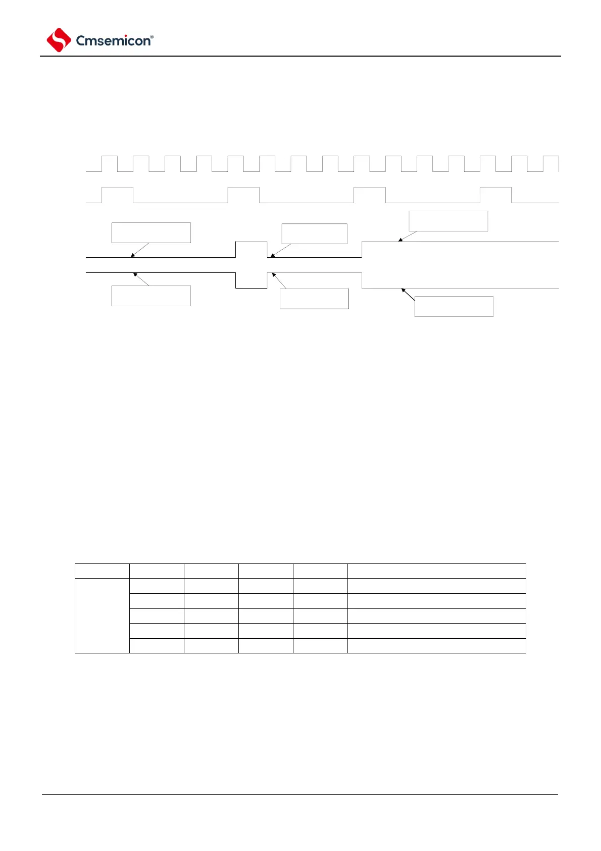
Figure 6-8 Output timing diagram
clk_epwm
timer_tout3
epwmo0
epwmo1
When OE0=0 and IE0=0 are
set, epwmo0 is low level
output
When OE1=0 and IE1=1 are
set, epwmo0 is high level
output
When OE0=1 and IE0=0
are set, epwmo0=tout3
When OE1=1 and IE1=0
are set, epwmo0=~tout3
When OE0=0 and IE0=1 are
set, epwmo0 is high level
output
When OE1=0 and IE1=0 are
set, epwmo0 is low level
output
6.3.3 Force truncation processing
EPWM can select CMP0 output, INTP0, through the EPWMSTC register bit1,0 input, along with the E
VENTC event, causes the EPWMO output to enter a forced truncation state.
(1) Occurrence of forced truncation
The INTP0 input and EVENTC events are truncated via the CMP0 output. By bit2(IN_EG) of
EPWMSTC register, it can select the rising or falling edge and enter the truncated state after 1 to 2
clocks. For details, please refer to Figure 6-9.
(2) Release of forced truncation
a) Software release: When bit3 (HS_SEL) of EPWMSTC register is 0, the software release mode is
used. Bit 0 (HZCLR) of EPWMSTR register is the clear bit of truncated status. When the truncated
status flag SHTFLG is high, if the HZCLR bit is set to 1, the truncated status flag SHTFLG goes
low and the forced truncated status is released.
b) Hardware release: When bit3 (HS_SEL) of EPWMSTC register is 1, the hardware release mode is
used. The forced truncation state is released by the edge of CMP0 output or INTP0 input.
Table 6-2 Table of operation Instructions for truncation signals