CMS32L051 User Manual |Chapter 5 Universal Timer Unit (Timer4)
www.mcu.com.cn 118 / 703
5.2.4 Timer data register mn (TDRmn)
This is a 16-bit register that can be used for switching between the capture function and the
comparison function. The operating mode is selected by the MDmn3~MDmn0 bits of the timer mode
register mn (TMRmn), and the capture function and the comparison function are switched.
TDRmn registers can be rewritten at any time.
This register can be read and written in 16-bit increments.
The SPLIT bit in 8-bit timer mode (timer mode registers m1, m3 (TMRm1, TMRm3) is 1), can read
and write TDRm1 registers and TDRm3 registers in 8-bit units, where TDRm1H and TDRm3H Used as
high 8 bits, TDRm1L and TDRm3L are used as low 8 bits.
After the reset signal is generated, the value of the TDRmn register changes to 0000H.
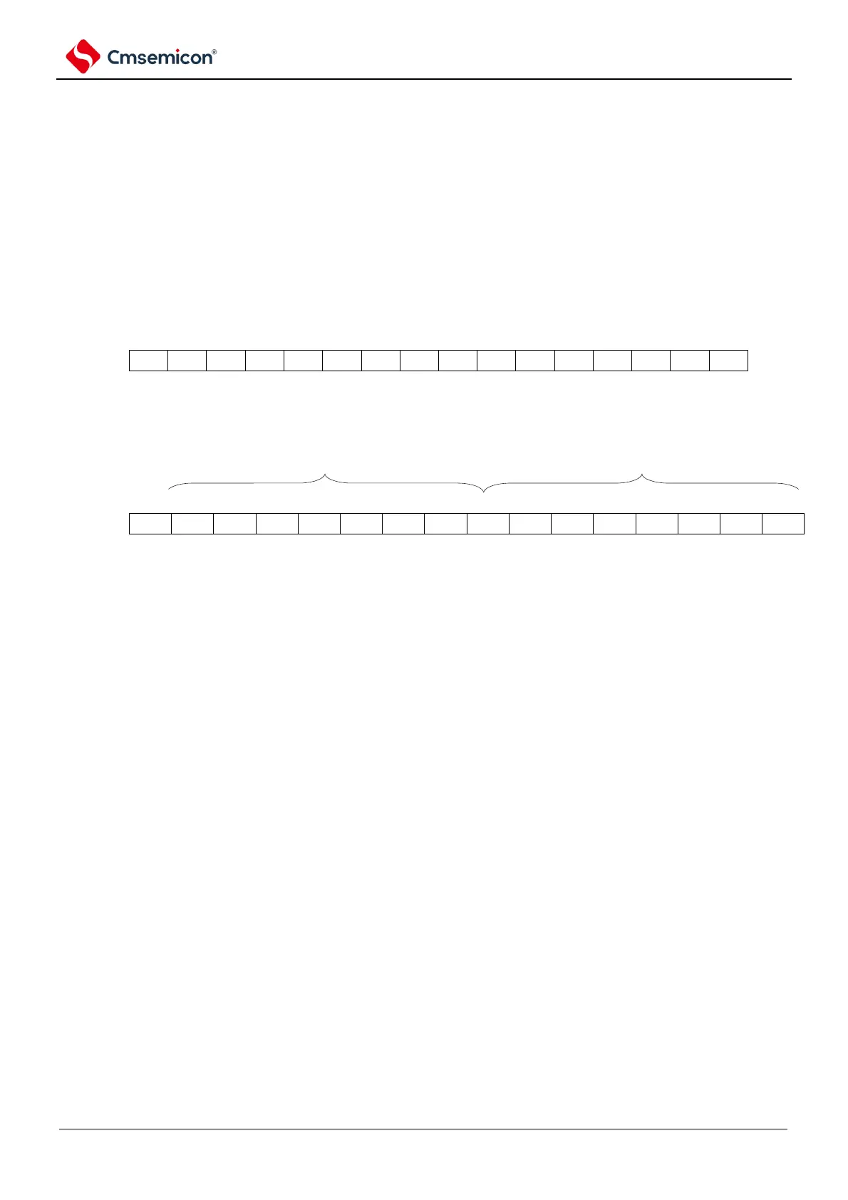
Figure 5-4 Format of timer data register mn(TDRmn) (n=0, 2)
Figure 5-5 Table of timer data registers mn (TDRmn) (n=1, 3)
(TDR01H can support 8-bit operation) (TDR01L can support 8-bit operation).
(i) The timer data register mn (TDRmn) is used as a case for comparison registers
The count is decremented from the config value of the TDRmn register, and when the count
value becomes 0000H, an interrupt signal (INTTMmn) is generated. The value of the TDRmn
register is held until it is overwritten.
Note: The TDRmn register set to the comparison function does not perform a capture operation even if the input captures
the trigger signal.
(ii) The timer data register mn (TDRmn) is used as a case for the capture register
The count value of the timer count register mn (TCRmn) is snapped to the TDRmn register by
input capture triggering.
The active edge of the TImn pin can be selected as the capture trigger signal. The selection of
capture triggers is set by timing mode register mn (TMRmn).
Remark: m: unit number (m=0,1) n: channel number (n=0~3).