CMS32L051 User Manual |Chapter 12 Universal Serial Communication Unit
www.mcu.com.cn 433 / 703
12.7.4 Handling steps when an error occurs during UART (UART0~UART 2) communication
The handling steps when an error occurs during UART (UART0~UART 2) communication are shown in
Figure 12-111and Figure 12-112.
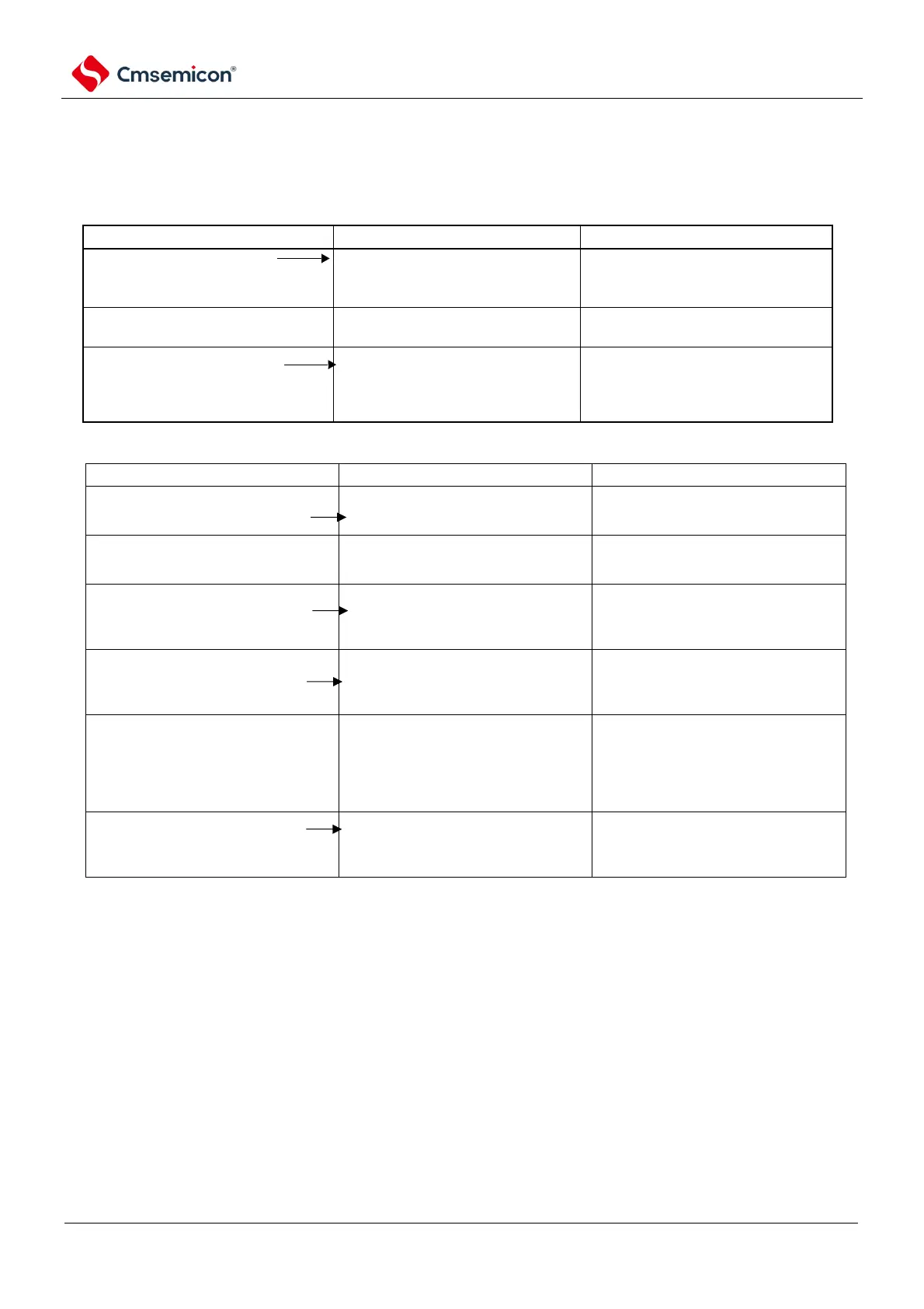
Figure 12-111 Processing steps when a parity error or overflow error occurs
Read the serial data register mn
(SDRmn).
The BFFmn bit of the SSRmn register
is 0 and channel n is receiverable.
This is to prevent overflow errors from
occurring when the next receive ends
during error handling.
Read the serial status register mn
(SSRmn).
Determine the type of error, and read
the value to clear the error marker.
Clear the trigger register mn to the
serial flag (SDIRmn) writes 1.
By writing the read value of the SSRmn
register directly to the SDIRmn register,
errors during read operations can only
be cleared.
Figure 12-112 Processing steps when a frame error occurs
Read the serial data register
mn(SDRMN).
The BFF m n bit of the SSRm n
register is 0 and channel n is
acceptable.
This is to prevent overflow errors
from ending the next reception
during mishandling.
Read the serial status register
mn(SSRmn).
Determine the error category, and
read the value to remove the error
marker.
Write the serial flag to clear the
trigger register mn
(SIRmn).
By writing the read value of the
SSRmn register directly to the
SDIRmn register, errors during read
operations can only be cleared.
Set the STmn bit of the serial
channel stop register m (STm) to "1".
The serial channel allows the Without
n bit of status register m (Herself m)
to be 0 and channel n is the running
stop state.
Synchronize processing with the
communicating party.
Because the start bit is offset, a
frame error can be considered to
have occurred. Therefore, it is
necessary to re-synchronize with the
communicating party and restart the
communication.
Set the SSmn bit of the serial
channel start register m (SSm) to "1".
The serial channel allows the SE m n
bit of status register m (Herself m) to
be 1 and channel n to be
operational.
Remarks m: Unit number (m=0, 1) n: Channel number (n=0~3) mn=00~ 03, 10~11.