CMS32L051 User Manual |Chapter 11 A/D Converter
www.mcu.com.cn 265 / 703
Chapter 11 A/D Converter
The number of analog input channels for A/D converters varies by product, and detailed pins refer to the
corresponding product data sheet.
(ANI0~ANI 3,
YEARS8~ANI1
4,
ANI16~ANI24,
ANI29,
ANI31~ANI33,
ANI36)
(ANI0~ANI 3,
YEARS8~ANI1
4,
ANI16~ANI24,
ANI27,ANI29)
(ANI0~ANI5,
ANI8~ANI14,
ANI16~ANI2
4,
ANI29,
ANI31~ANI3
4,
ANI36)
(ANI0~ANI6,
ANI8~ANI14,
ANI16~ANI2
4,
ANI27,
ANI29~ANI3
2)
Note 1. (-A) is limited to BJHH502Axxx-A series products. (-B) indicates that it is limited to BJHH502Axxx-B series
products.
11.1 Function of A/D converter
An A/D converter is a converter that converts an analog input to a digital value, and an A/D converter has
the following functions.
conversion with 12-bit resolution
Select a channel of analog inputs from ANI0 to ANI36 and a temperature sensor and repeat the A/D
conversion with 12-bit resolution. For every A/D conversion that ends, an interrupt request (INTAD) is generated
(the case of a select mode).
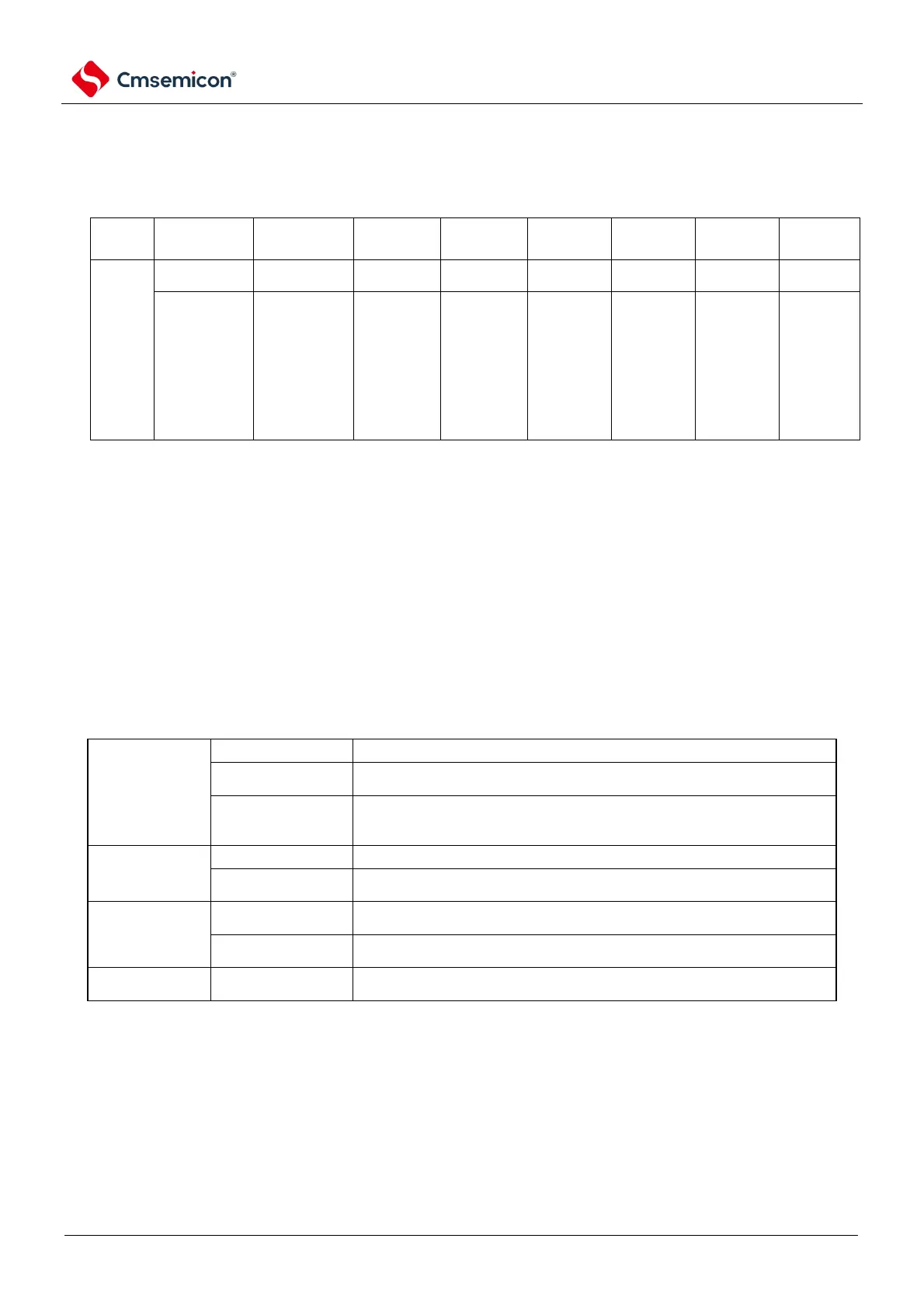
Various A/D conversion modes can be set through the following combination of modes.
Start the conversion with software operation.
Hardware trigger no-
wait mode
Start the conversion by detecting a hardware trigger.
Hardware trigger wait
mode
In the transition standby state when the A/D power supply is cut off, the power
supply is turned on by detecting the hardware trigger, and the conversion
automatically begins after the A/D power supply stabilization waiting time.
Select 1 channel of analog inputs for A/D conversion.
A/D conversion of analog inputs for 4 channels is performed sequentially. Four
consecutive channels from ANI0 to ANI1 5 can be selected as analog inputs.
Performs 1 A/D conversion on the selected channel.
Continuous conversion
mode
Continuous A/D conversion of the selected channel until it is stopped by the
software.
The sampling time can be selected via the ADSMPWAIT register, which uses
four conversion clocks (f
AD
) by default.