CMS32L051 User Manual |Chapter 5 Universal Timer Unit (Timer4)
www.mcu.com.cn 131 / 703
5.3.6 Timer channel start register m (TSm).
The TSm register is a trigger register that initializes the timer count register mn (TCRmn) and sets the
start of each channel count operation. If each position is 1, the timer channel allows the corresponding bit
of the status register m (TEm) to be set to 1. Because the TSmn bit, TSHm1 bit, and TSHm3 bit are the
trigger bits, if they become operational enable (TEmn, TEHm1, TEHm3=1), the TSmn, TSHm1, and
TSHm3 bits are immediately cleared.
The TSm register is set via 16-bit memory operation instructions.
The lower 8 bits of the TSm register can be set with TSmL and via 8-bit memory operation instructions.
After the reset signal is generated, the value of the TSm register changes to 0000H.
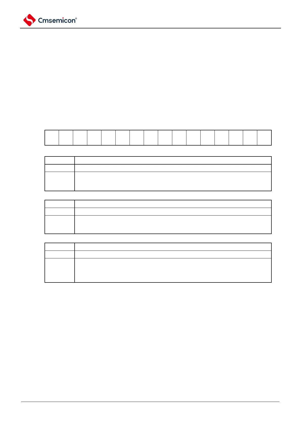
Figure 5-15 Table of Timer Channel Start Register m (TSm)
Symbol
15 14 13 12 11 10 9 8 7 6 5 4
3 2 1` 0
TSm
The operation of the high 8-bit timer in channel 3 for 8-bit timer mode enable (start) to trigger
Place the TEHm3 position 1 into the count allow state.
If the counting of TCRm3 registers is started while counting is allowed, interval timer mode is
entered (refer to Table 5-5 of Start Timing of 5.5.2 Counters).
The operation of the high 8-bit timer in channel 1 for 8-bit timer mode enable (start) to trigger
Place the TEHm1 position 1 into the count allow state.
If the counting of TCRm1 registers is started while counting is allowed, interval timer mode is
entered (refer to Table 5-5 of Start Timing of 5.5.2 Counters).
The operation of channel n enable (start) to trigger
Place the TEmn position 1 into the count allow state. The start of counting of TCRmn registers
in the enable state of counting varies by mode of operation (refer to Table 5- of Start Timing of
5.5.2 Counters 5). When channels 1 and 3 are in 8-bit timer mode, TSm1 and TSm3 are 8 low
The operation of the bit timer enable (start) to trigger.
Note 1 You must set bit15~12, 10, 8~4 to 0.
2. When switching from the function of not using the TImn pin input to the function of using the TImn pin input, from
setting the timer mode register mn (TMRmn) to the TSmn (TSHm1, TSHm3) position 1 until the following period
of wait:
When the TImn pin noise filter is active (TNFENmn=1): 4 operating clocks (f
MCK
).
When the TImn pin noise filter is invalid (TNFENmn=0): 2 operating clocks (f
MCK
).
Note: 1. The read value of the TSm register is always 0.
2.m: unit number (m=0,1) n: channel number (n=0~3).