CMS32L051 User Manual |Chapter 4 Clock Generation Circuit
www.mcu.com.cn 68 / 703
4.3.3 Clock operation status control register (CSC)
This is a register that controls the operation of the high-speed system clock, the high-speed internal
oscillator clock, and the secondary system clock (except for the low-speed internal oscillator clock). Set the
CSC register via an 8-bit memory operation instruction.
After the reset signal is generated, the value of this register changes to C0H.
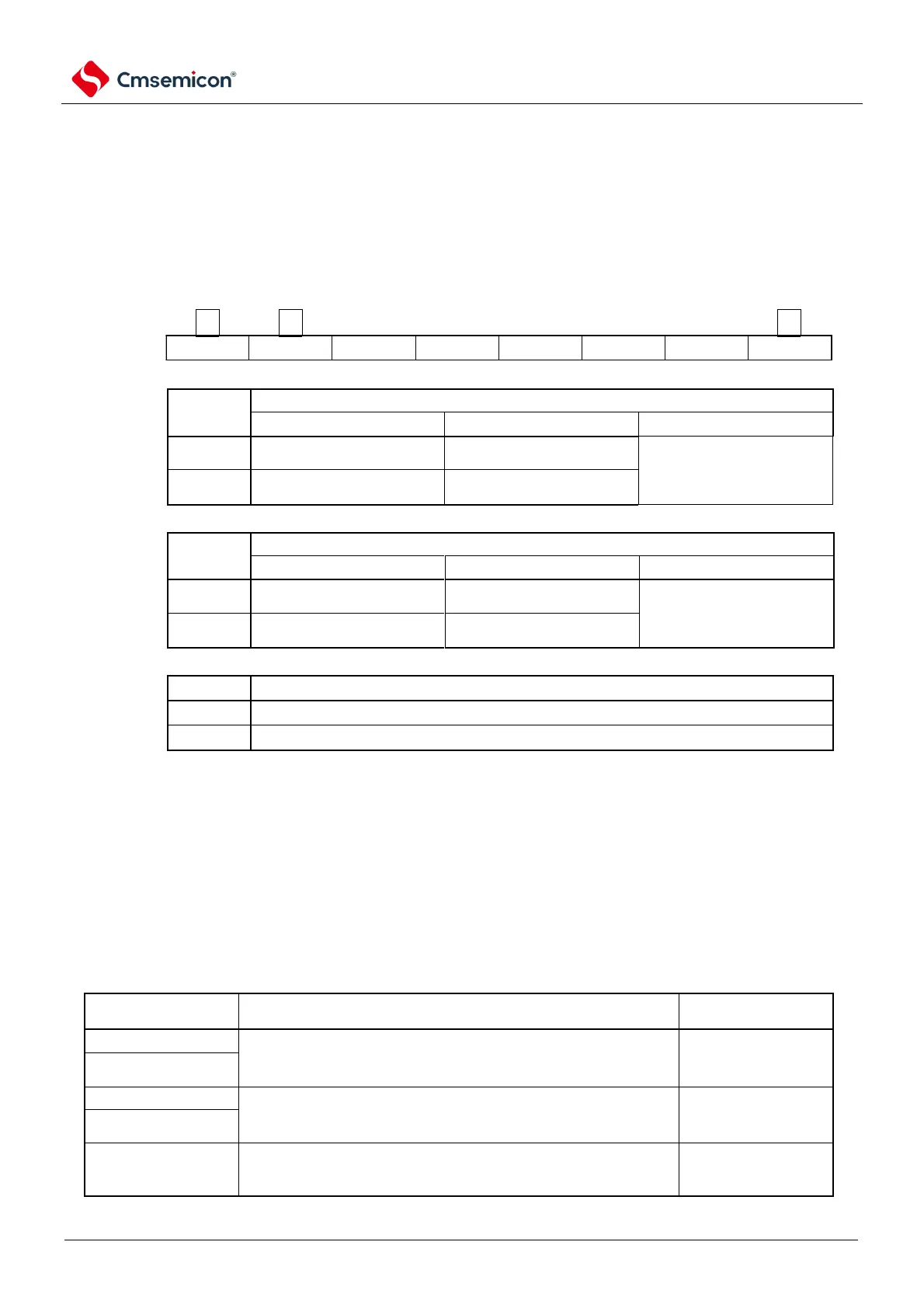
Figure 4-4 Format of clock operating status control register
Address: 40020401H After reset: C0H R/W
symbol
CSC
Operational control of the high-speed system clock
External clock input mode
X1 oscillation circuit runs
The external clock of the
EXCLK pin is valid
X1 oscillation circuit stops
The external clock on the
EXCLK pin is invalid
Operational control of the subsystem clock
External clock input mode
XT1 oscillation circuit runs
The external clock of the
EXCLKS pin is valid
XT1 oscillation circuit stops
The external clock of the
EXCLKS pin is invalid
Operation control of the high-speed internal oscillator clock
High-speed internal oscillator runs
High-speed internal oscillator stops
Note 1 After the reset is released, the CSC register must be set after the clock run-mode control register (CMC) is set.
2. After the reset is released and before the MSTOP position is 0, the oscillation settling time selection register
(OSTS) must be set. However, when using the OSTS register with the initial value, there is no need to set the
OSTS register.
3. To start the X1 oscillation by setting the MSTOP bit, the oscillation settling time of the X1 clock must be confirmed
through the state register (OSTC) of the oscillation settling time counter.
4. To start the XT1 oscillation by setting the XSTOP bit, you must wait through the software for the oscillation settling
time required by the subsystem clock.
5. The clock selected as the CPU/Peripheral Hardware Clock (fCLK) cannot be stopped through the CSC registers.
6. For the register flag setting and pre-stop conditions for stopping clock oscillation (external clock input is invalid),
refer to Table 4-2.
Table 4-2 Clock stop method
Conditions before the clock stops (invalid external clock input)
Set the flag of the CSC
register
The CPU/peripheral hardware clock operates on a clock other than
the high-speed system clock.
(CLS=0 and MCS=0, or CLS=1).
External master system
clock
The CPU/peripheral hardware clock operates on a clock other than
the secondary system clock.
(CLS=0)
High-speed internal
oscillator clock
The CPU/peripheral hardware clock runs on a clock other than the
high-speed internal oscillator clock.
(CLS=0 and MCS=1, or CLS=1).