CMS32L051 User Manual |Chapter 5 Universal Timer Unit (Timer4)
www.mcu.com.cn 130 / 703
5.3.5 Timer channel enable status register m (TEm)
TEm registers are registers that represent the enabled or stopped state of each channel timer
operation.
Each of the TEm registers corresponds to each of the timer channel start register m (TSm) and the
timer channel stop register m (TTm). If each position of the TSm register is set to 1, the corresponding bit
of the TEm register is set to 1. If each bit of the TTm register is set to 1, the corresponding bit is cleared
to 0.
The TEm register is read via 16-bit memory operation instructions.
The lower 8 bits of the TEm register can be read with TEmL and via 8-bit memory operation
instructions. After the reset signal is generated, the value of the TEm register changes to 0000H.
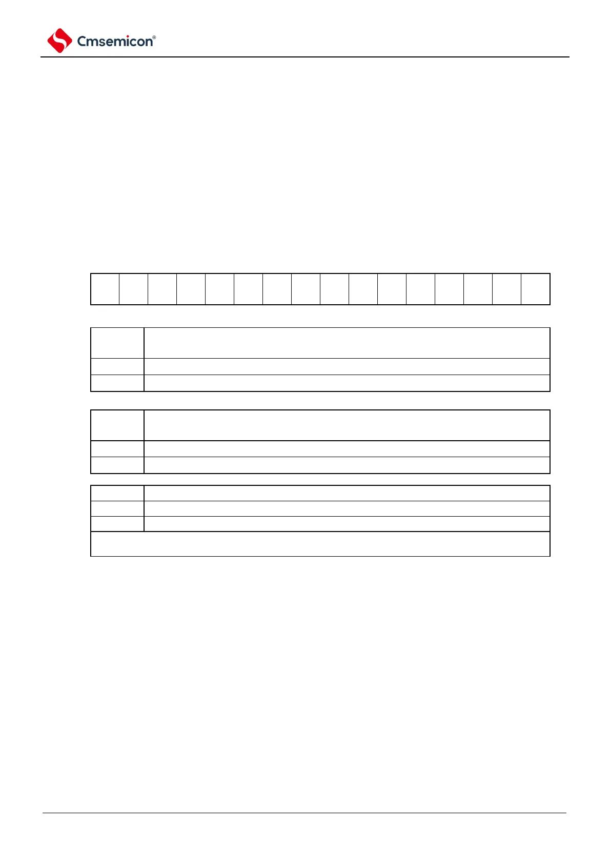
Figure 5-14 Timer Channel Enable Status Registers m (TEm)
Symbol
15 14 13 12 11 10 9 8 7 6 5 4 3 2 1
0
Has
When channels 1 and 3 are in 8-bit timer mode, TEm1 and TEm3 indicate the operating enable or stop
state of the low-8-bit timer.