CMS32L051 User Manual |Chapter 7 Real-Time Clock
www.mcu.com.cn 235 / 703
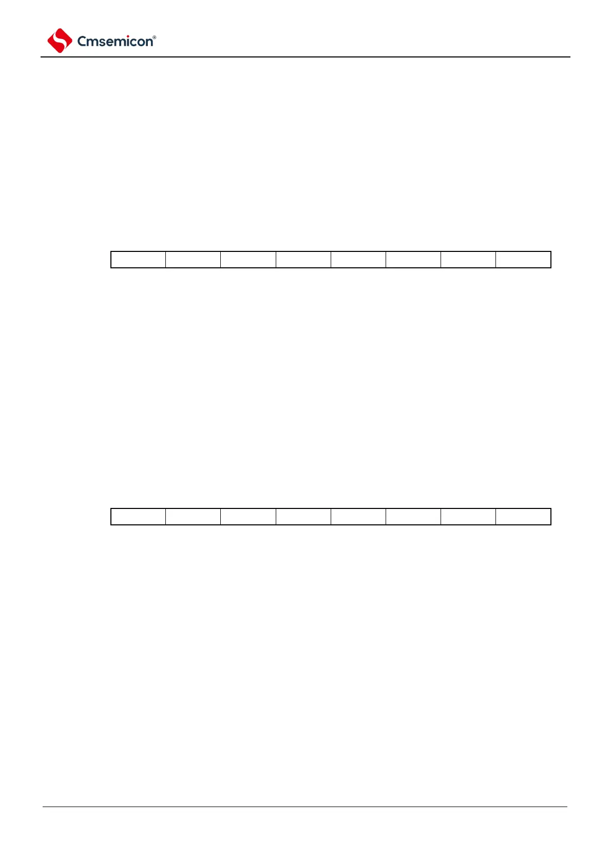
7.3.13 Alarm minute register (ALARMWM)
This is the register that sets the alarm for minutes.
The ALARMWM register is set via an 8-bit memory operation command. After the reset signal is
generated, the value of this register becomes 00H.
Note The decimal 00 to 59 must be set in BCD code. If you set a value outside the range, the alarm is not detected.
Figure 7-14 Format of alarm minute register (ALARMWM)
Address: 0x40044F5AH After reset: 00H R/W
Symbol
7 6 5 4 3 2 1
0
ALARMWM
7.3.14 Alarm hour register (ALARMWH)
This is the register that sets the alarm for hours.
The ALARMWH register is set via an 8-bit memory operation command. After the reset signal is
generated, the value of this register changes to 12H.
However, the value of this register is 00H if the AMPM bit is set to 1 after reset.
Note The decimal 00~23 or 01~12, 21~32 must be set in BCD code. If you set a value outside the range, the alarm is not
detected.
Figure 7-15 Format of Alarm Hour Register (ALARMWH)
Address: 0x40044F5BH After reset: 12H R/W
Symbol
7 6 5 4 3 2 1
0
ALARMWH
Note When the AMPM bit is selected as 0 (12-hour system), bit5 (WH20) of the ALARMWH register represents AM (0)
/PM (1).