CMS32L051 User Manual |Chapter 4 Clock Generation Circuit
www.mcu.com.cn 99 / 703
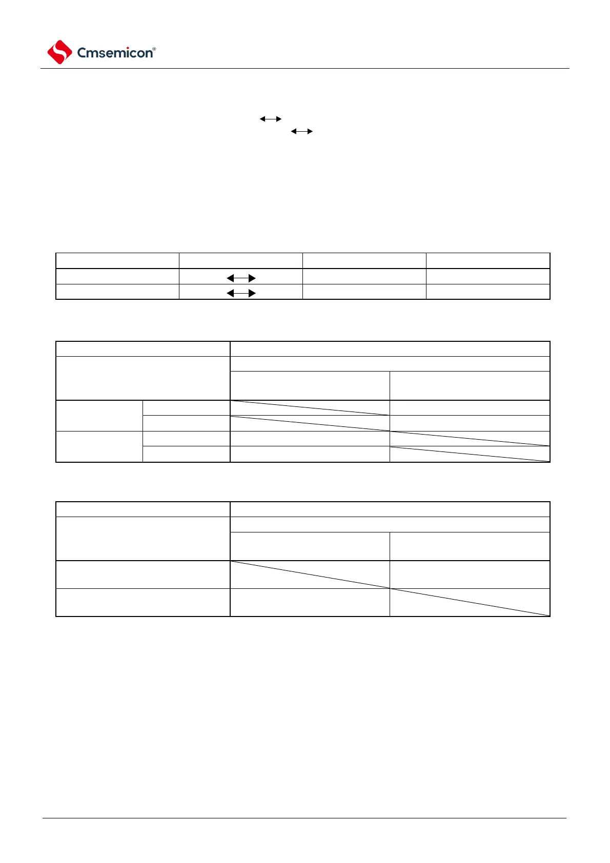
4.6.6 Time required to switch between CPU clock and main system clock
CPU clock switching (master system clock) can be performed by setting bit6 and bit4 (C SS, MCM0)
of the system clock control register (CKC). Secondary system clock) and the switching of the main
system clock (high-speed internal oscillator clock high-speed system clock).
Instead of making the actual switch immediately after overwriting the CKC registers, several clocks
continue to run at the pre-switching clock after changing the CKC registers (refer to Table 4-5~Table
4-7).
It can be determined by bit7 (CLS) of the CKC register whether the CPU is running from the primary
system clock or the secondary system clock. The bit5 (MCS) of the CKC register can tell whether the
master system clock is running on a high-speed system clock or a high-speed internal oscillator clock.
If you switch the CPU clock, you switch the peripheral hardware clock at the same time.
Table 4-5 Time required to switch the master system clock
Note 1 The number of clocks in Table 4-6and Table 4-7is the number of CPU clocks before switchover.
2. The number of clocks in Table Table 4-6Table Table 4-7number of clocks rounded to the fractional part.
For example, the main system clock is switched from the high-speed system clock to the high-speed internal
oscillator clock (f-IH=8MHz and fMX=10MHz oscillation is selected).
2fMX/fIH = 2 (10/8) = 2.5 3 clocks