CMS32L051 User Manual |Chapter 4 Clock Generation Circuit
www.mcu.com.cn 98 / 703
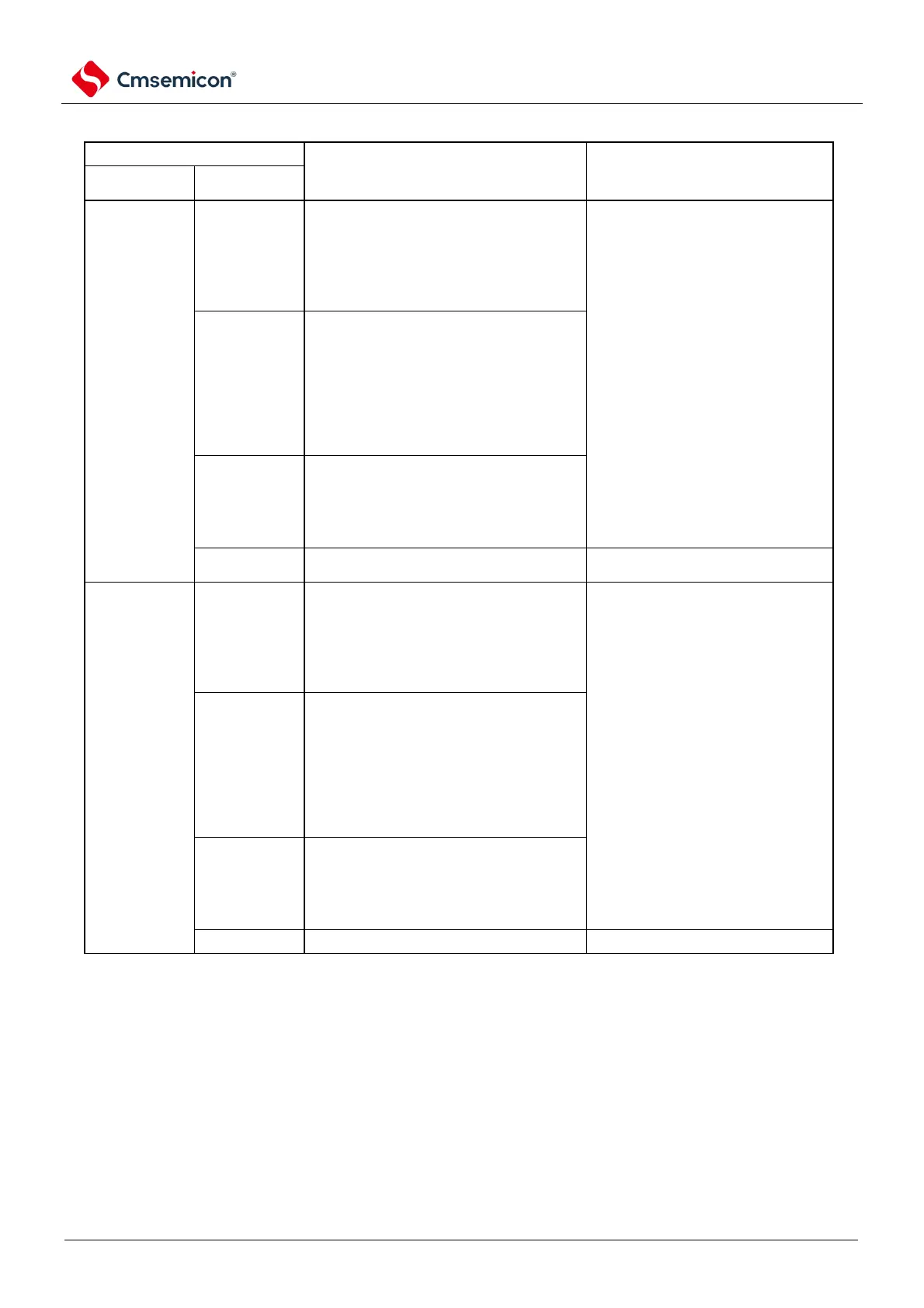
Table 4-4 Transfers of CPU clocks (2/2)
Conditions before transfer
High-speed
internal
oscillator
The high-speed internal oscillator is
oscillating and the high-speed internal is
chosen
Can stop the oscillation of XT1
(XTSTOP=1).
The oscillator clock acts as the master
system clock.
The X1 oscillation is stable and the high-
speed system clock is chosen as the main
system
OSCSEL=1, EXCLK=0, MSTOP=0
After the oscillation stabilization time
External master
system clock
Leave the external clock of the EXCLK pin
input active and select the high-speed
system clock as the master system clock.
OSCSEL=1, EXCLK=1, MSTOP=0
MCS=1
High-speed
internal
oscillator
The high-speed internal oscillator is
oscillating and the high-speed internal is
chosen
Input to the external subsystem clock
can be set to invalid
The oscillator clock acts as the master
system clock.
The X1 oscillation is stable and the high-
speed system clock is chosen as the main
system
OSCSEL=1, EXCLK=0, MSTOP=0
oscillation stabilization time
External master
system clock
Leave the external clock of the EXCLK pin
input active and select the high-speed
system clock as the master system clock.
OSCSEL=1, EXCLK=1, MSTOP=0
MCS=1