CMS32L051 User Manual |Chapter 3 System Structure
www.mcu.com.cn 57 / 703
Chapter 3 System Structure
3.1 Overview
This product system consists of the following parts:
•
2 AHB bus master:
-
Cortex-M0+
-
Enhanced DMA
•
4 AHB bus slavas:
-
FLASH memory
-
SRAM memory 0
-
SRAM memory 1
-
AHB to APB Bridge, containing all APB interface peripherals
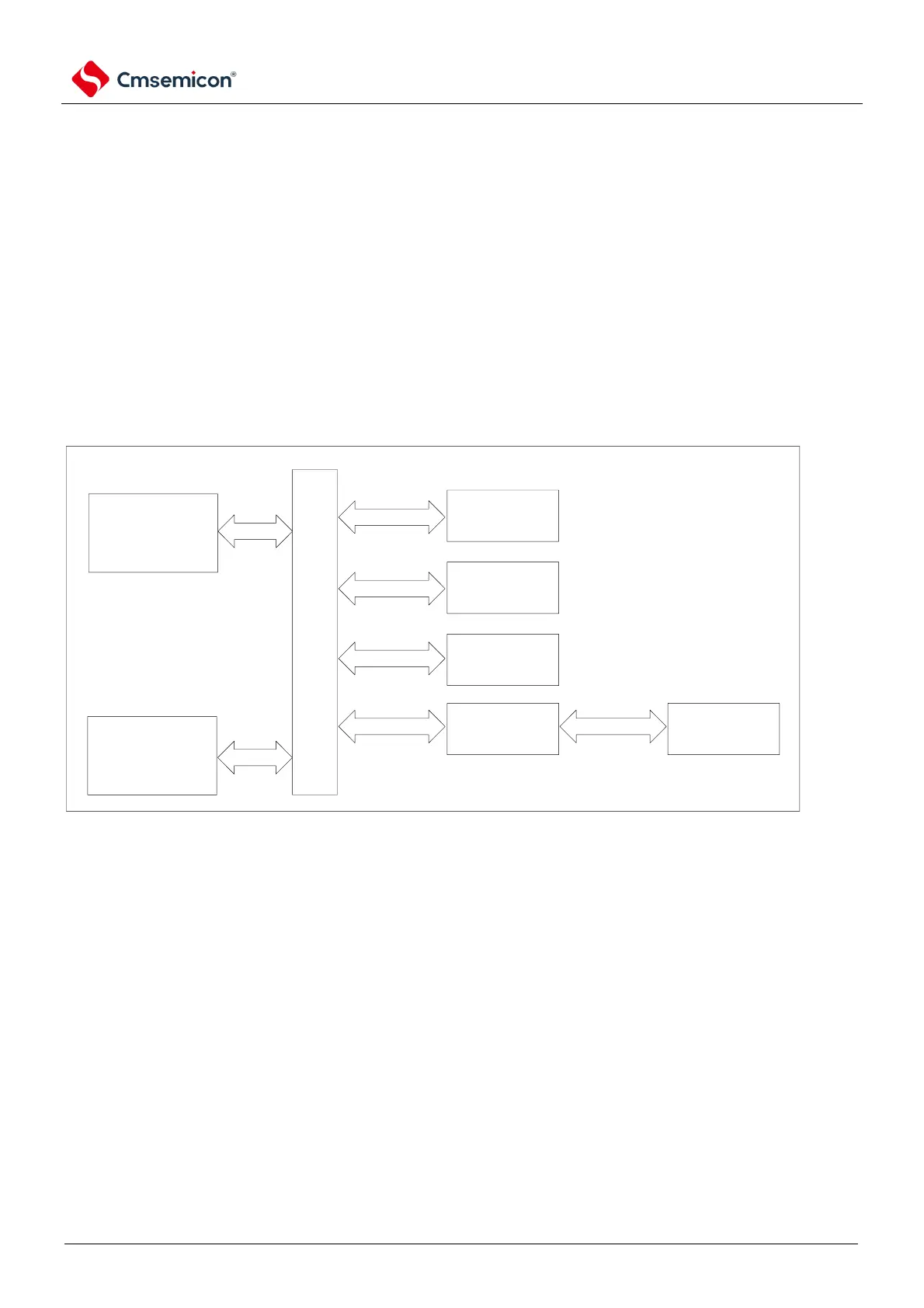
Figure 3-1 Schematic diagram of the system structure
•
System bus: This bus connects the system bus (peripheral bus) of the Cortex-M0+ core to a bus
matrix that coordinates access between the core and DMA.
•
DMA bus: This bus connects the AHB master interface of the DMA with a bus matrix that coordinates
the CPU and DMA access to SRAM, flash memory, and peripherals.
•
Bus matrix: The bus matrix coordinates access arbitration between the core system bus and the DMA
master bus, with a fixed priority and a high DMA priority.
•
AHB to APB Bridge: AHB to APB Bridge provides a synchronous connection between the AHB and
APB buses. For address mappings of the different peripherals connected to each bridge, refer to
Table Table 3-1.