CMS32L051 User Manual |Chapter 5 Universal Timer Unit (Timer4)
www.mcu.com.cn 154 / 703
5.6.3 Cautions for channel output operation
(1) Change of TOm, TOEm, TOLm, and TOMm register settings during timer operation
The operation of the timer (the operation of the timer count register mn (TCRmn) and the timer data
register mn (TDRmn)) and the TOmn output circuit are independent of each other. Thus, the timer output
register m (TOm), the timer output enable register m (TOEm) and the timer output level register m (TOLm)
config value changes do not affect the operation of the timer, you can change the config value while the
timer is running. However, in order to output the expected waveform from the TOmn pin during the
operation of each timer, it must be set to the values of the register settings shown in 5.8 and 5.9 for each
run content example.
If you change the settings of the TOEm register and the TOLm register in addition to the TOm register
before and after generating the timer interrupt (INTTMmn) signal for each channel, it is based on the timer
interrupt (INTTMmn) being generated Whether the signal changes before or after generation, the
waveform of the TOmn pin output may be different.
Note m: unit number (m=0,1) n: channel number (n=0~3).
(2) The initial level of the TOmn pin and the output level after the timer starts operating
The timer output register m (TOm) is written before the port output is enabled and in the state of
disabling the timer output (TOEmn=0), and set to the timer output enabled state (TOEmn=1) after
changing the initial level. The change in the output level of the TOmn pin is shown below.
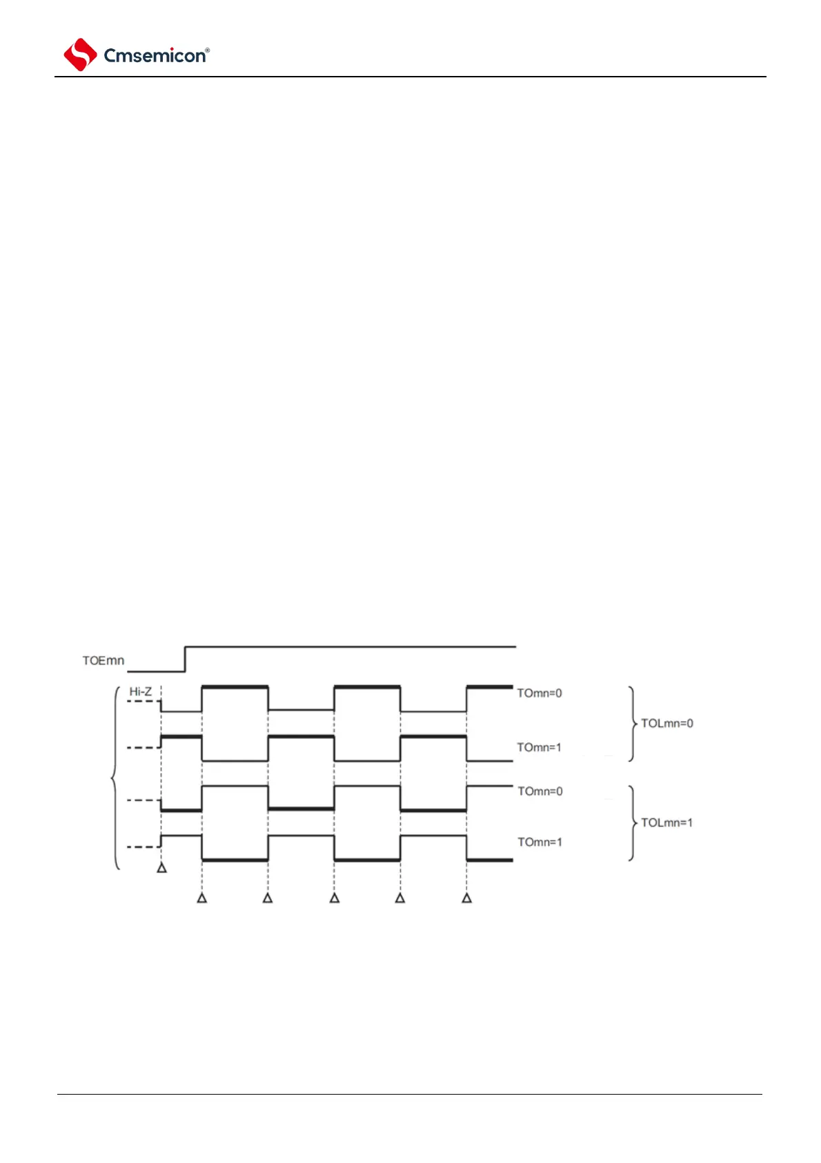
(a) When starting operation in the master channel output mode (TOMmn=0).
In the master channel output mode (TOMmn=0), the timer output level register m (TOLm) is not set.
If the operation of the timer begins after setting the initial level, the output level of the inverting TOmn pin
is reversed by generating an alternating signal.
Figure 5-33 Output state of TOmn pin at alternate output (TOMmn=0)