CMS32L051 User Manual |Chapter 7 Real-Time Clock
www.mcu.com.cn 226 / 703
7.3.4 Real-time clock control register1 (RTCC1)
This is the 8-bit register that controls the alarm interrupt function and the counter waits. The RTCC1
register is set via an 8-bit memory operation command. After the reset signal is generated, the value of
this register becomes 00H.
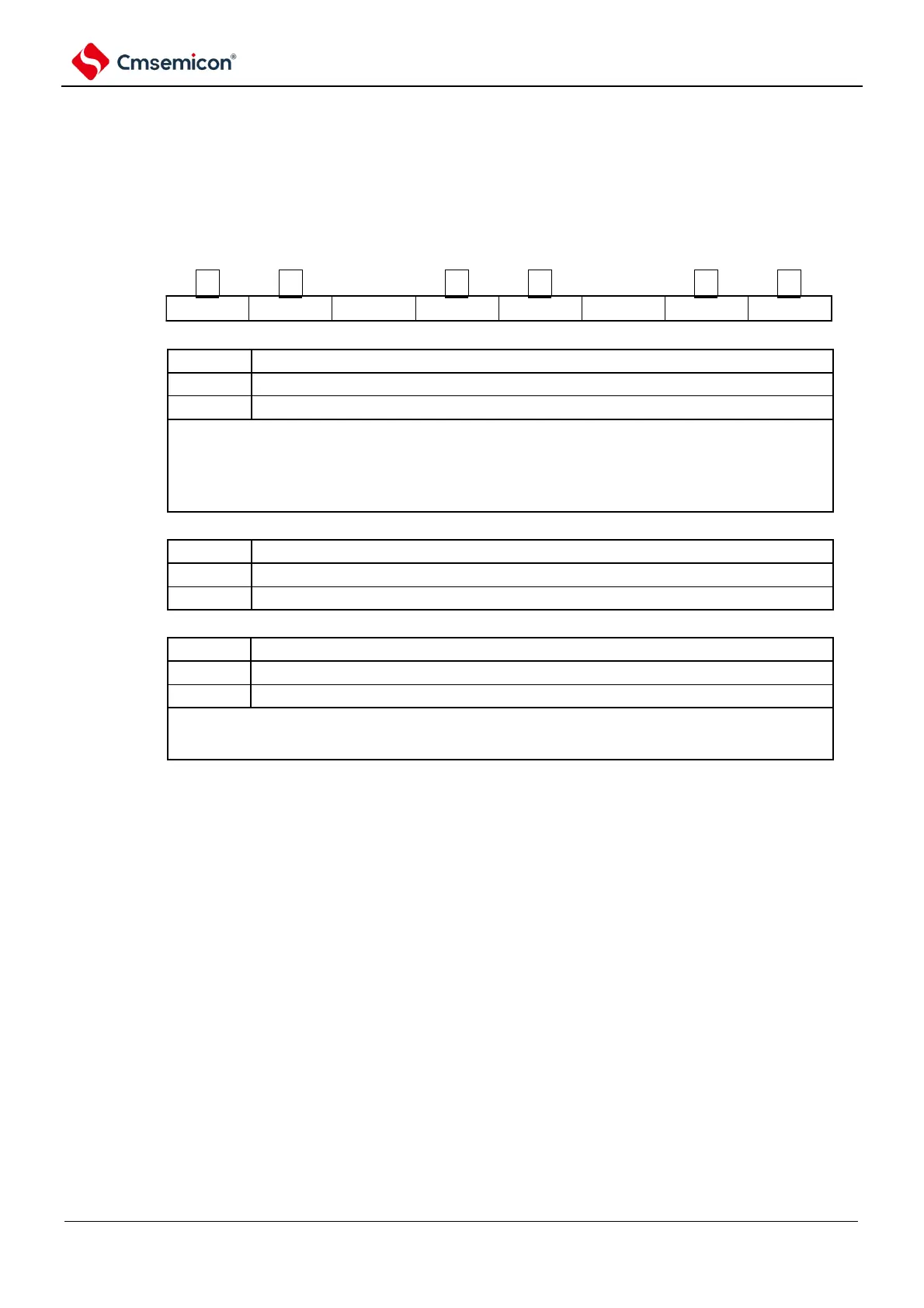
Figure 7-5 Format of real-time clock control register 1 (RTCC1) (1/2)
Address: 0x40044F5E After reset: 00H R/W
symbol
RTCC1
Alarm clock operation control
Consistent operation is invalid.
Consistent operation is valid.
To set the WALE bit while the counter is running (RTCE=1) and the NULLE bit is 1, it must be overridden
after setting the INTRTC to disable interrupt handling through the interrupt mask flag register. And the
WAFG flag and the RTCIF flag must be cleared after rewriting. To set each alarm register (AL flag for
RTCC1 register, alarm clock minute register (ALARMWM), alarm hour register (ALARMWH) and alarm
clock day registers (ALARMWW)), the WALE set to 0 (consistent operation is invalid).
Operation control of alarm interrupt (INTRTC) function
No alarm clock consistent interruptions are generated.
Generates an alarm clock consistent interrupt.
Alarm detection status flag
Alarm clock is inconsistent.
Alarm clock consistency detected.
This is a status flag that indicates that the alarm clock is detected consistently. Valid only when the WALE
bit is 1 and becomes 1 when the alarm clock is detected to be consistent and 1 f
RTC
clock has passed.
Clear this flag by writing 0 to this flag. The action to write 1 is invalid.