CMS32L051 User Manual |Chapter 14 Serial interface IICA
www.mcu.com.cn 496 / 703
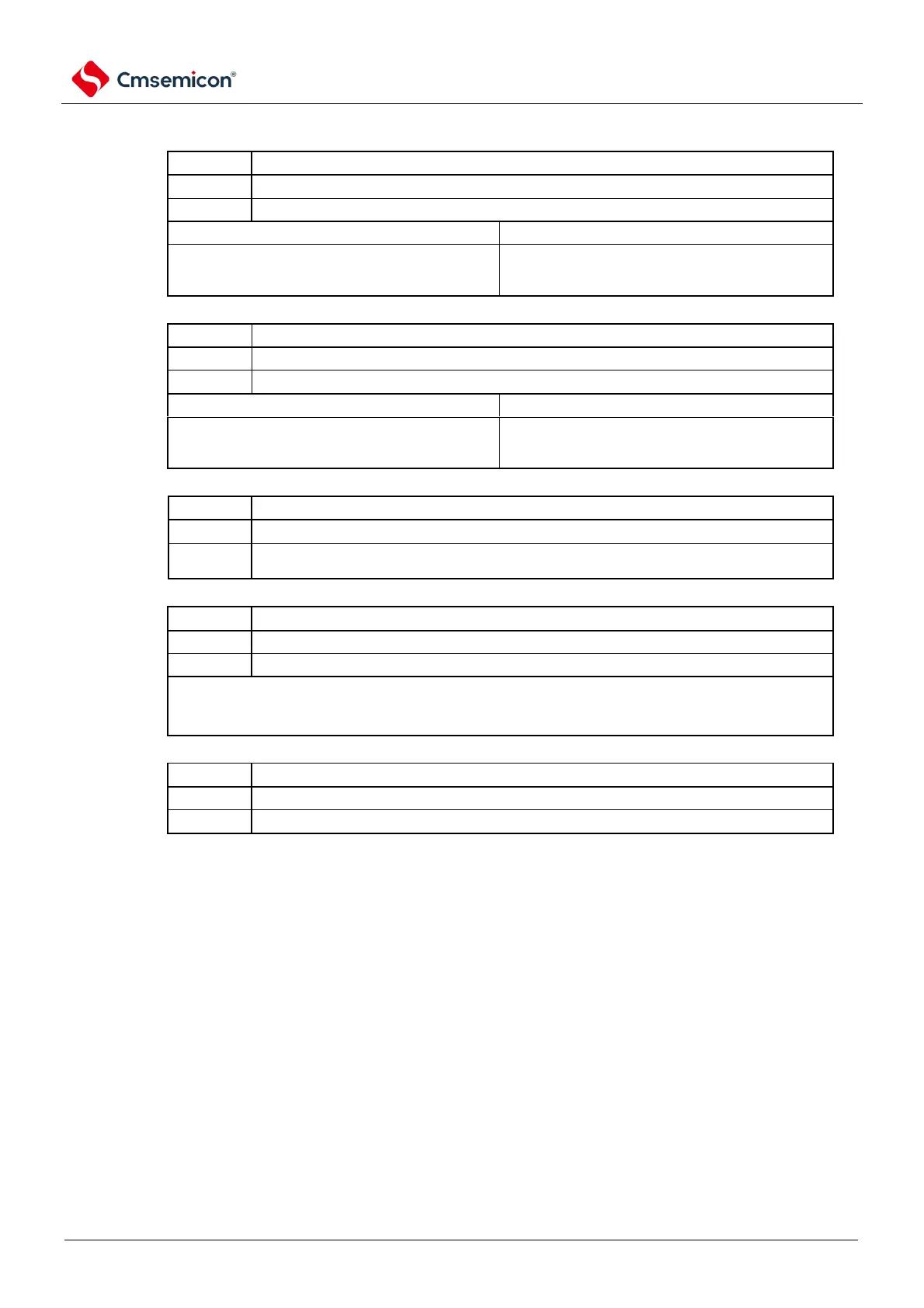
Figure 14-9 Format of IICA control register n1 (IICCTLn1) (2/2)
Level detection of the SCLAn pin (valid only when the IICEn bit is 1).
A low SCLAn pin is detected.
A high SCLAn pin is detected.
Clear condition (CLDn=0).
SCLAn pin is low
the IICEn bit is 0 (stop running).
SCLAn pin is high
Level detection of the SDAAn pin (valid only when the IICEn bit is 1).
A low SDAAn pin is detected.
An SDAAn pin high is detected.
Clear condition (DADn=0).
SDAAn pin is low
the IICEn bit is 0 (stop running).
SDAAn pin is high
Switching of operating modes
Operates in standard mode (maximum transfer rate: 100kbps).
Operates in Fast Mode (Max Transfer Rate: 400kbps) or Enhanced Fast Mode (Max
Transfer Rate: 1Mbps).
Operation control of digital filters
Digital filters must be used in fast mode or enhanced
fast mode. Digital filters are used to remove noise.
Whether the DFCn bit is 1 or clear 0, the transmit clock remains unchanged.
Operate the clock (f
MCK
) control
Select f
CLK
(
CLK
).
Select f
CLK
/2(20MHz<f
CLK
).
Note 1.The maximum operating frequency of the IICA operating clock (f
MCK
) is 20MHz (Max.). IICA control register n1
(IICCTLn1) must only be used when the f
CLK
exceeds 20MHz bit0 (PRSn) is set to 1.
2. In the case of setting the transmission clock, it is necessary to pay attention to the minimum operating frequency
of f
CLK
. The minimum operating frequency of the f
CLK
for the serial interface IICA depends on the operating
mode.
Fast mode: f
CLK
= 3.5MHz (Min.)
Enhanced Fast Mode: f
CLK
= 10MHz (Min.)
Standard mode: f
CLK
= 1MHz (Min.)
Note 1. IICEn: IICA controls bit7 of register n0 (IICCTLn0).
2. n=0