CMS32L051 User Manual |Chapter 12 Universal Serial Communication Unit
www.mcu.com.cn 308 / 703
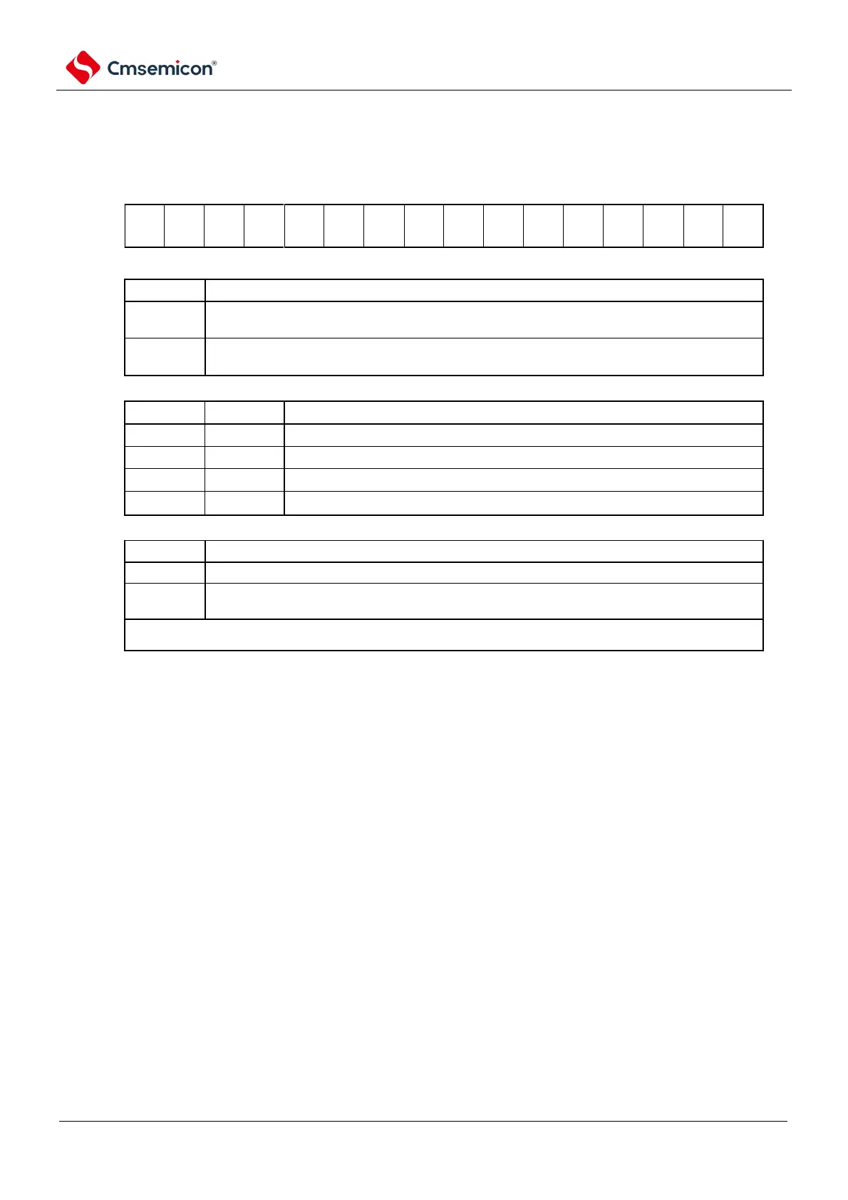
Figure 12-7 Format of serial mode register mn (SMRmn) (2/2)
Address: 40041110H(SMR00)~40041116H(SMR03) After reset: 0020HR/W
40041550H(SMR10)~40041552H(SMR11)
Symbol
15 14 13 12 11 10 9 8 7 6 5 4 3 2 1 0
SMRmn
Level inversion control of received data for channel n in UART mode
Detect the falling edge as the starting bit.
The input communication data is not reversed.
Detect the rising edge as the starting point.
The input communication data is reversed.
Setting of the channel n operating mode
Channel n interrupt source selection
The end of the transfer is interrupted
Buffer empty interrupt
(Occurs when data is transferred from the SDRmn register to the shift register).
In continuous transmission, if the MDmn0 bit is 1 and the data for SDRmn is empty, the next sent data is
made.
Note 1 SMR01, SMR03, SMR11, registers only.
Note You must set bit13 to 9, 7, 4, 3 (SMR00, SMR02, SMR10 registers are bit13~6, 4, 3) to 0, and set bit5 to 1.
Remark m: Unit number (m=0, 1) n: Channel number (n=0~3) p: SSPI number (p=00, 01, 10, 11, 20, 21)
q: UART number (q=0~2) r: IIC number (r=00, 01, 10, 11, 20, 21)