EasyManua.ls Logo

Cmsemicon CMS32L051 - Page 640

Default Icon
703 pages
Print Icon
To Next Page IconTo Next Page
To Previous Page IconTo Previous Page
Loading...
V1.2.2
CMS32L051 User Manual |Chapter 21 Reset Function
www.mcu.com.cn 640 / 703
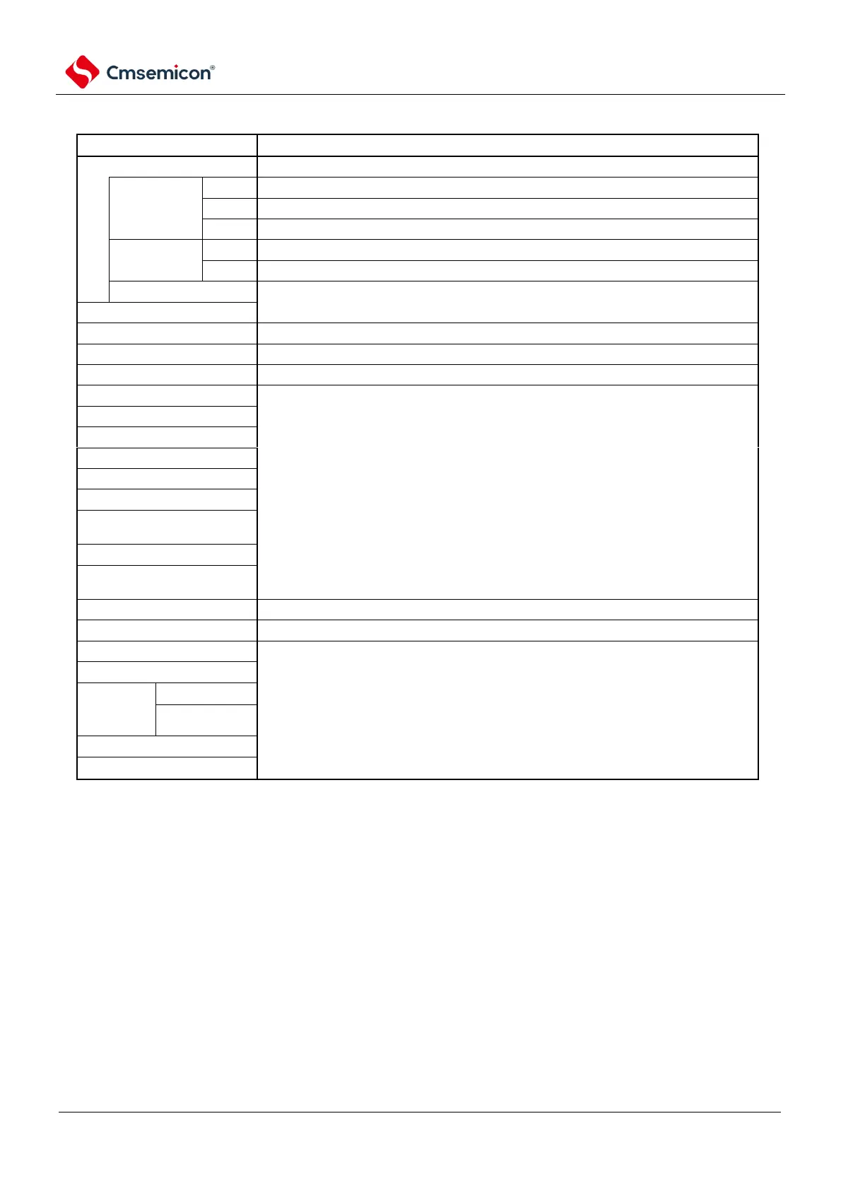
Table 21-1 Operational status during reset
Item
During reset
System clock
Stop supplying clocks to the CPU.
The master
system clock
f
IH
Stop running.
f
X
Stops operation (pins X1 and X2 are in input port mode).
f
EX
The clock input is invalid (the pin is in input port mode).
Auxiliary
system clock
f
XT
Can run.
f
EXS
The clock input is invalid (the pin is in input port mode).
f
II
Stop running.
CPU
Code flash
Stop running.
RAM
Stop running.
Port (latch)
High Impedance
Note
1
Universal timer unit
Stop running.
Real-time clock (RTC).
1 5-bit interval timer
Watchdog timer
Clock output/buzzer output
A/D converter
Universal Serial
Communication Unit (SCI)
Serial Interface (IICA).
Data Transfer Controller
(DMA).
Power-on reset function
It can perform detection runs.
Voltage detection function
It can be operated when the LVD is reset. In other resets, stop running.
External interrupts
Stop running.
Key interrupt function
CRC
operation
function
High-speed CRC
Generic CRC
RAM parity function
SFR protection function
Note 1 Port pins P 10, P26, P 40, P137 become the following states:
High impedance during an external reset or POR reset. High during other reset periods (internal pull-up resistor is
connected).
Remark
f
IH
: High-speed internal oscillator
clock
f
X
: X1 oscillating clock
f
EX
: External master system clock
f
XT
: XT1 oscillating clock
f
EXS
: External subsystem clock
f
II
: Low-speed internal
oscillator clock

Table of Contents

Related product manuals