CMS32L051 User Manual |Chapter 14 Serial interface IICA
www.mcu.com.cn 492 / 703
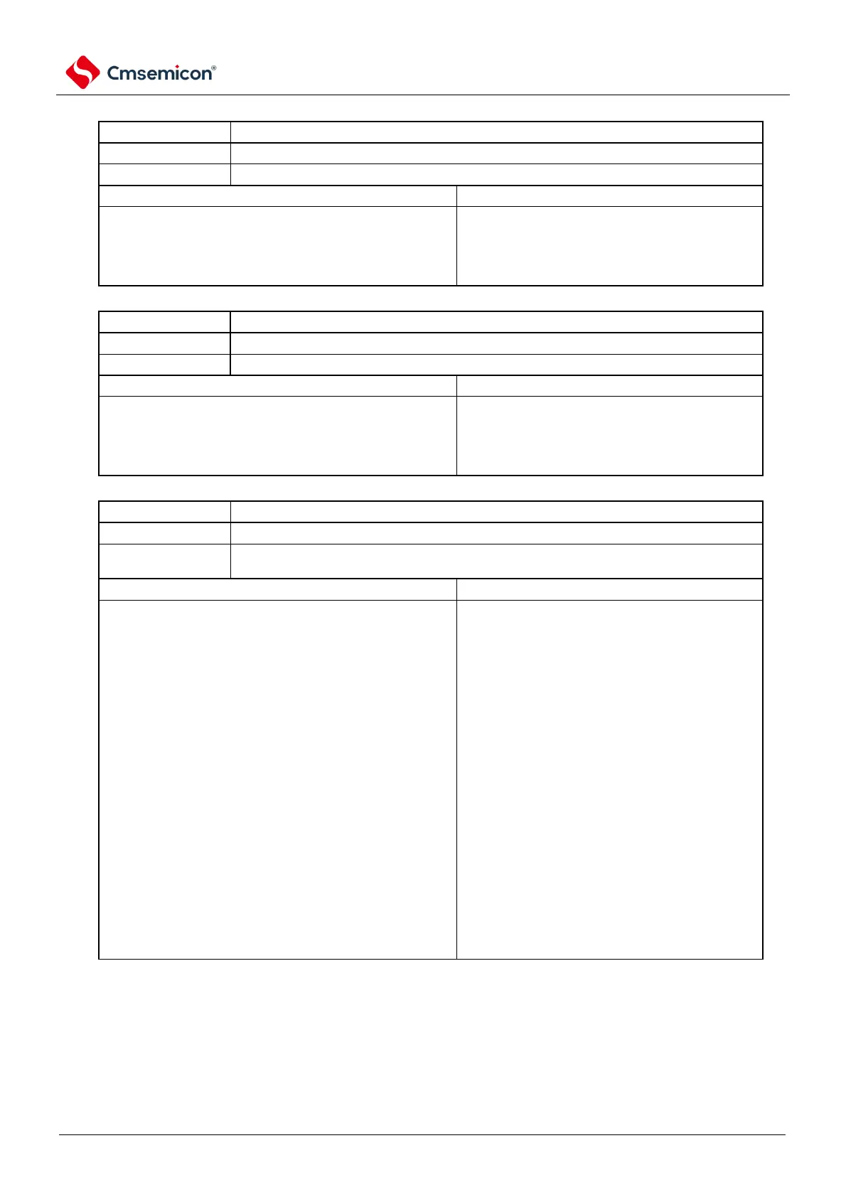
Figure 14-7 Format of IICA status register n (IICSn) (2/3)
Receive detection of expansion codes
The extension code was not received.
The extension code is received.
Clear condition (EXCn=0).
LRELn bit being 1 (exit communication).
IICEn bit changes from 1 to 0 (stop running).
address data
is 0000 or 1111
(Set on the rising edge of the 8th clock).
Detection of address matches
Clear condition (COIn=0).
LRELn bit being 1 (exit communication).
IICEn bit changes from 1 to 0 (stop running).
When receiving address and local station address
(slave address register n (SVAn)) is the same (Set
on the rising edge of the 8th clock).
Send/receive status detection
It is in the receive state (except for the send state). Set the SDAAn line to high impedance.
It is in the sending state. Set to output the value of the SOn latch to the SDAAn line
(effective after the falling edge of the 9th clock of byte 1).
Clear condition (TRCn=0).
< Master and slave devices>
When generating a start condition
LRELn bit being 1 (exit communication).
When the LSB (transmission direction indication
bit) output of the first byte (address transmission) is
0 (master transmission).
IICEn bit changes from 1 to 0 (stop running).
due to WRELn bit being 1 (release wait).
the ALDn bit changes from 0 to 1 (arbitration
failed).
When the LSB (transmission direction indication
bit) of the first byte (address transmission) of the
master device is "1" (slave transmission).
non-participation in communication (MSTSn,
EXCn, COIn=0).
(Transfer Direction Indicator Bit) of the first
byte outputs 1
When the LSB (transmission direction indication bit) of the
1st byte is entered as "0"
Note If bit 3 (TRCn) of IICA status register n (IICSn) is "1" (transmit status), if bit 5 (WRELn) of IICA control register n0
(IICCTLn0) is set to "1" at the 9th clock " to release the wait, the SDAAn line is set to high impedance after clearing the
TRCn bit (receive state). The wait must be released by writing "1" to the TRCn bit of the IICA shift register n (transmit
state).
Remark 1. LRELn: Bit6 of the IICA control register n0 (IICCTLn0).
IICEn: Bit7 of the IICA control register n0 (IICCTLn0).
2. n=0