CMS32L051 User Manual |Chapter 5 Universal Timer Unit (Timer4)
www.mcu.com.cn 171 / 703
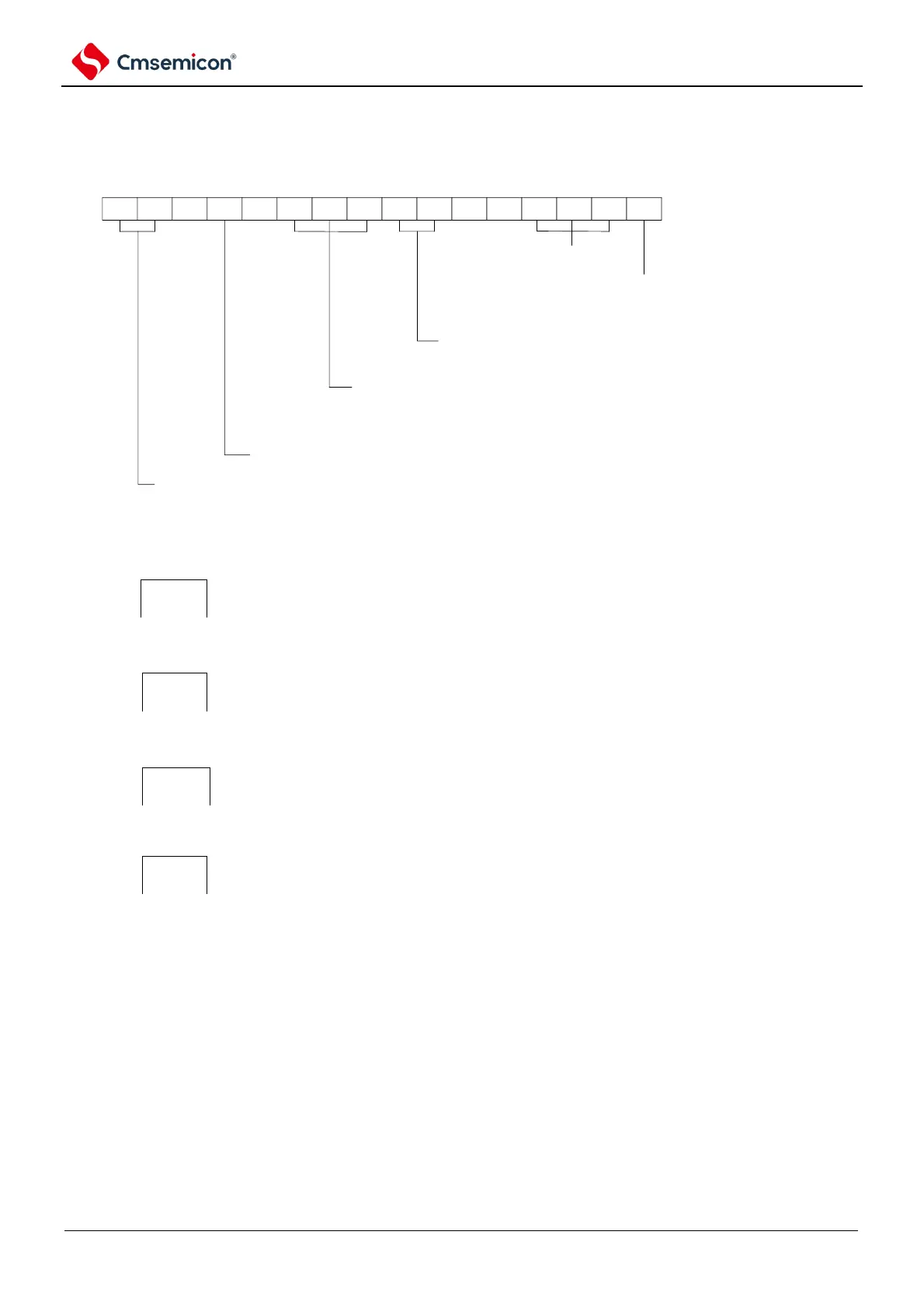
Figure 5-50 Example of register setting content for operation as a frequency divider
(a) Timer mode register 00 (TMR00).
CKS001
1/0
CKS000
0
0
CCS00
1
0
STS002
0
STS001
0
STS000
0
CIS001
1/0
CIS000
1/0
0 0
MD003
0
MD002
0
MD001
0
MD000
1/0
14 13 12 11 10 9 8 7 6 5 4 3 2 1 015
TMR00
operation mode of Channel N
000B: Interval Timer
Timn Pin input edge selection
00B: Detect falling edge
01B: Detect rising edge
10B: Detect both edges
11B: reserved
start trigger selection
000B: only select software to start trigger.
Count clock selection
1: Select TI00 pin output valid edge
operational clock (fMCK) selection
00B: select CK00 as operational clock of Channel 0.
10B: select CK01 as operational clock of channel 1.
operation configuration when start counting
0: when start counting, not to generate INTTMmn and do not generate inverted Phase Timer output.
1: when start counting, generate INTTMmn and generate inverted Phase Timer output.