CMS32L051 User Manual |Chapter 4 Clock Generation Circuit
www.mcu.com.cn 104 / 703
(1) Continuous operation mode
In continuous operation mode, the high-speed internal oscillator clock frequency correction
operation is carried out all the time. The FCMD bit of the HOCOFC register is set to 0, which is a
continuous operation mode.
The FCST bit of the HOCOFC register is set to 1 when the high-speed internal oscillator clock
frequency correction Operation begins. Similarly, the high-speed internal clock frequency correction
Operation stops when the FCST bit is set to 0.
After the high-speed internal clock frequency correction action, the rising edge frequency counter
of the reference clock (fSUB/2 9) begins counting and stops counting on the rising edge of the next
reference clock (fSUB/2
9
). (frequency measurement phase).
The count value is then compared to the expected value and the correction value adjustment is
made as described below. (Frequency correction phase)
When the count value is greater than expected: the correction value is -1
The count value is more than expected hours: the correction value is +1
When the count value is within the expected range: the correction value is maintained
(high-speed internal clock frequency correction ends)
When the FCIE bit of the HOCOFC register is set to 1, a high-speed internal oscillator clock
frequency correction interrupt is generated after the high-speed internal oscillator clock frequency
correction is completed. In continuous operation mode, the high-speed internal oscillator clock
frequency correction function repeats the frequency measurement phase and the frequency correction
phase until the high-speed internal oscillator clock frequency correction function is stopped.
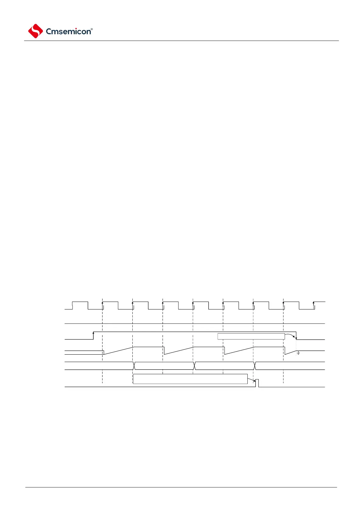
Figure 4-21 is a timing diagram of the continuous operation mode.
Figure 4-21 Continuous operation mode timing diagram
Reference
clock
(fsub/2^9)
CRST
(Action enabling
position)
20 bit count
register
"0000000B"
Correction
value
[6:0]
"0000001B" "0000010B"
"0000010B"
+1 +1
keep
Intermediate
value of counter
keep
CRST clear: software clear.
CRMD
(Action mode bit)
Continuous action mode "0"
High speed internal
frequency correction
completion interrupt
Interrupt generation: when CRIE bit is 1, fHOCO pulse with 1
cycle width will be output when correction is completed.