CMS32L051 User Manual |Chapter 16 Enhanced DMA
www.mcu.com.cn 582 / 703
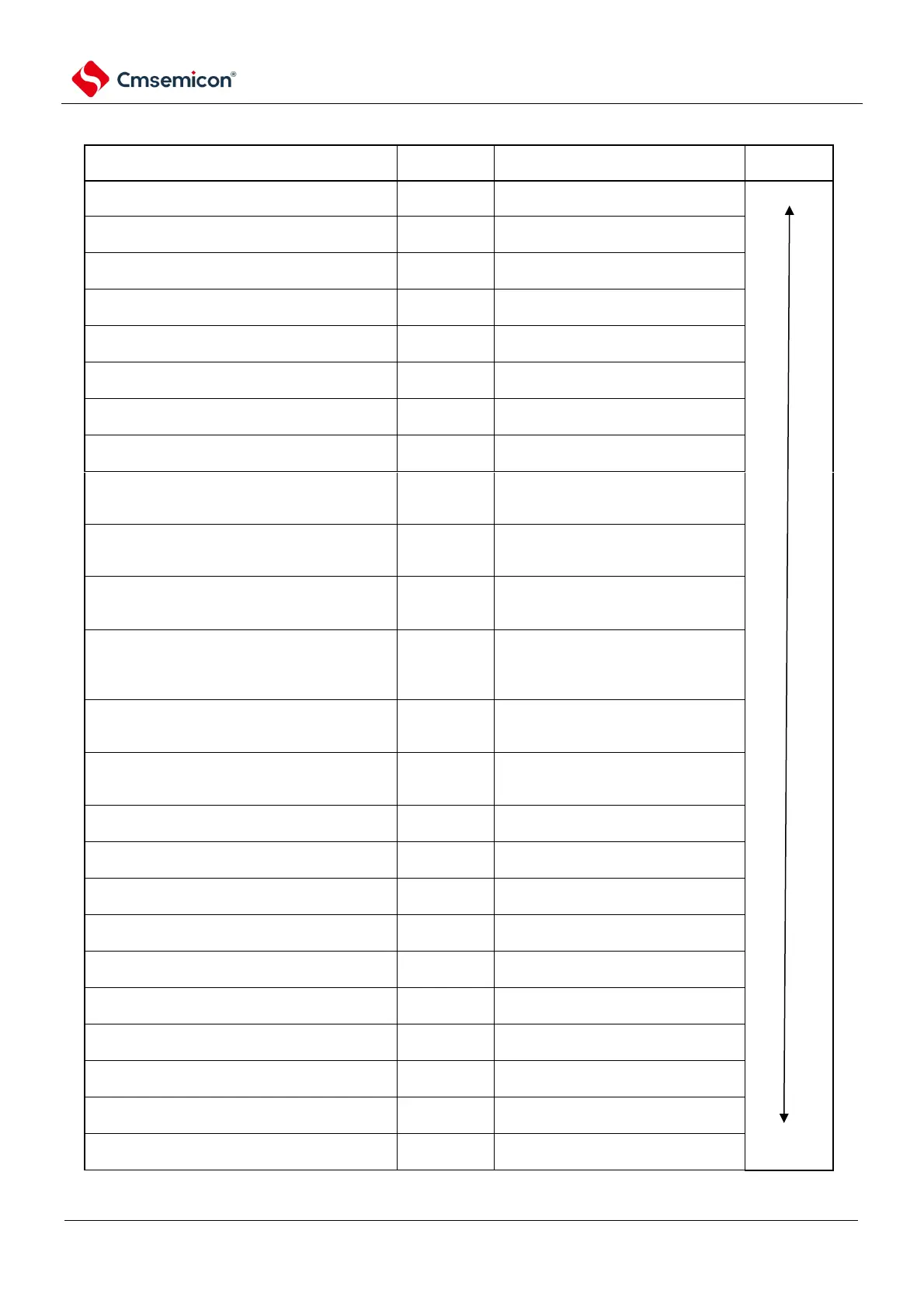
Table 16-5 DMA startup source and vector address
DMA start source (the source where the interrupt
request occurred).
The address of the vector
Flash read-write erase ends
The setting address of the DMABAR
register is +00H
The setting address of the DMABAR
register is +01H
The setting address of the DMABAR
register is +02H
The setting address of the DMABAR
register is +03H
The setting address of the DMABAR
register is +04H
The setting address of the DMABAR
register is +05H
The setting address of the DMABAR
register is +06H
The setting address of the DMABAR
register is +07H
The end of transmission received by UART0 /
the end of transmission of SSPI01 or the end of
transmission of buffer NULL/IIC01
The setting address of the DMABAR
register is +08H
The end of the UART0 transmission / the end of
the SSPI00 transmission or the end of the buffer
NULL/IIC00 transmission
The setting address of the DMABAR
register is +09H
The end of transmission received by UART1 /
the end of transmission of SSPI11 or the end of
transmission of buffer NULL/IIC11
The setting address of the DMABAR
register is +0AH
End of transmission for UART1 transmission/end
of transmission for SSPI10 or end of
transmission for buffer NULL/IIC10/end of
transmission for SPI
The setting address of the DMABAR
register is +0BL
The end of transmission received by UART2 /
the end of transmission of SSPI21 or the end of
transmission of buffer NULL/IIC21
The setting address of the DMABAR
register is +0CH
The end of the UART2 transmission / the end
of the SSPI20 transmission or the end of the
buffer null/IIC20 transmission
The DMABAR register is set to address
+0DH
IICA0 communication ends.
The setting address of the DMABAR
register is +0EI
A 15-bit interval timer generates a count interrupt
The setting address of the DMABAR
register is +0FF
Timer40 ends with the count of channel 0 or
capture
The setting address of the DMABAR
register is +10H
Timer40 for channel 1 counts or captures end
The setting address of the DMABAR
register is +11H
Timer40 for channel 2 counts or snaps ends
The setting address of the DMABAR
register is +12H
Timer40 ends with the count or snap of channel 3
The setting address of the DMABAR
register is +13H
Timer41 ends counting or snapping of channel 0
The setting address of the DMABAR
register is +14H
Timer41 ends with the counting or snapping of
channel 1
The setting address of the DMABAR
register is +15H
Timer41 ends with the count or snap of channel 2
The setting address of the DMABAR
register is +16H
Timer41 ends with the counting or snapping of
channel 3
The setting address of the DMABAR
register is +17H