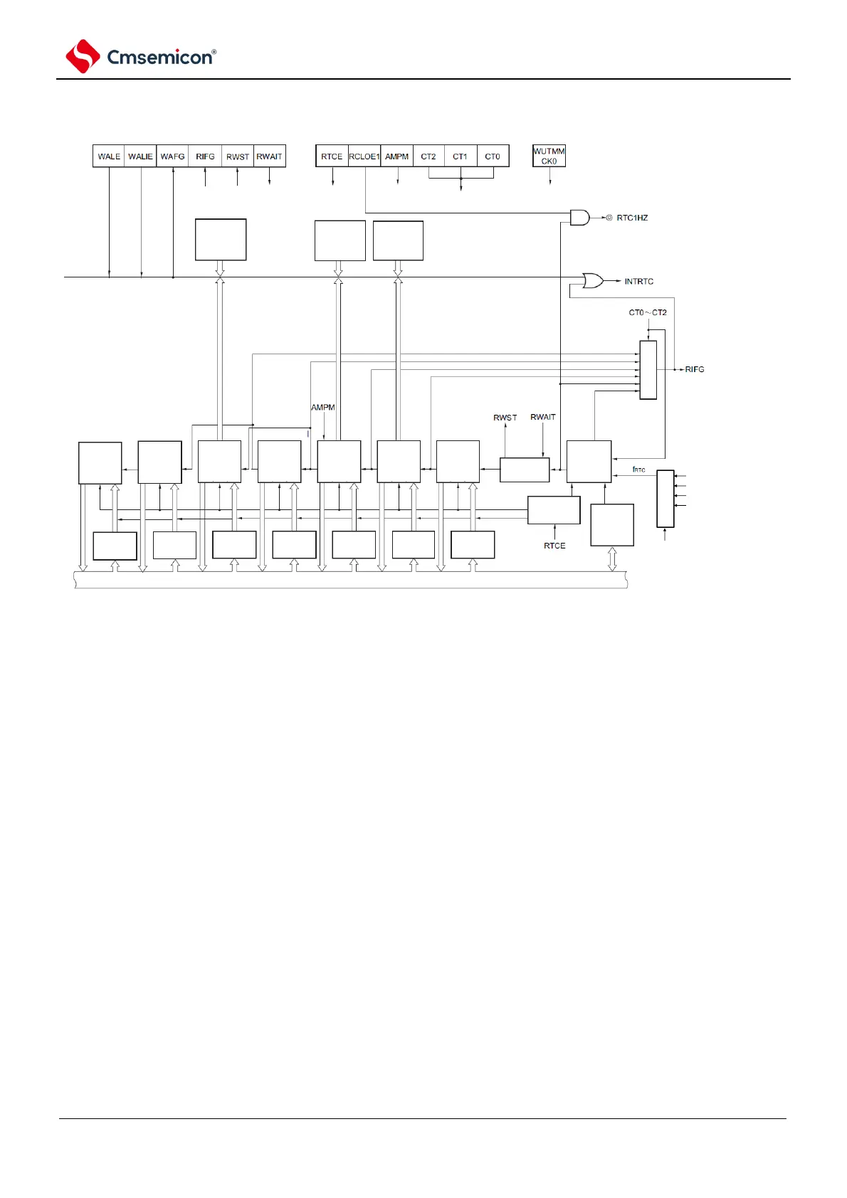
选
择
器
fSUB
fIL
fMX frequency division clock
fHOCO frequency division clock
RTCCL7,6,RTCCKS1,0
real time clock control register 1 real time clock control register 0
secondary system provide mode control
register (OSMC)
alarm week
register
(ALARMWW)
(7bits)
alarm hour
regsiter
(ALARMWH)
(6 bits)
alarm minute
register
(ALARMWM)
(7 bits)
same
year count
register
(YEAR)
(8 bits)
month
count
register
(MONTH)
(5 bits)
week count
regsiter
(WEEK)
(3 bits)
Day count
regsiter
(DAY)
(6 bits)
hour count
register
(HOUR)
(6 bits)
minute
count
regsiter
(MIN)
(7 bits)
second
count
regsiter
(SEC)
(7 bits)
wait control
internal count
regsiter
(16 bits)
countig enable/
disable circuit
clock
deviation
calibration
register
(SUBCUD)
(8 bits)
buffer buffer
buffer buffer buffer buffer buffer
Internal bus
selector
selector
1 year
1 month
1 day 1 hour
1
minute
1
second
0.5
seconds
Note Only the fmx/fhoco -system clock (f
SUB
=32.768kHz)
after the selection of fmx/f hoco. As a real-time clock running clock, the counting of years, months, weeks, days,
hours, minutes, and seconds can be performed. When selecting a low-speed internal oscillator clock (f
IL
=15kHz),
only a fixed-cycle interrupt function can be used.
The fixed-period interrupt interval when selecting f
IL
is calculated using the following formula:
Fixed period (value selected by the RTCC0 register) f
SUB
/f
IL