CMS32L051 User Manual |Chapter 12 Universal Serial Communication Unit
www.mcu.com.cn 310 / 703
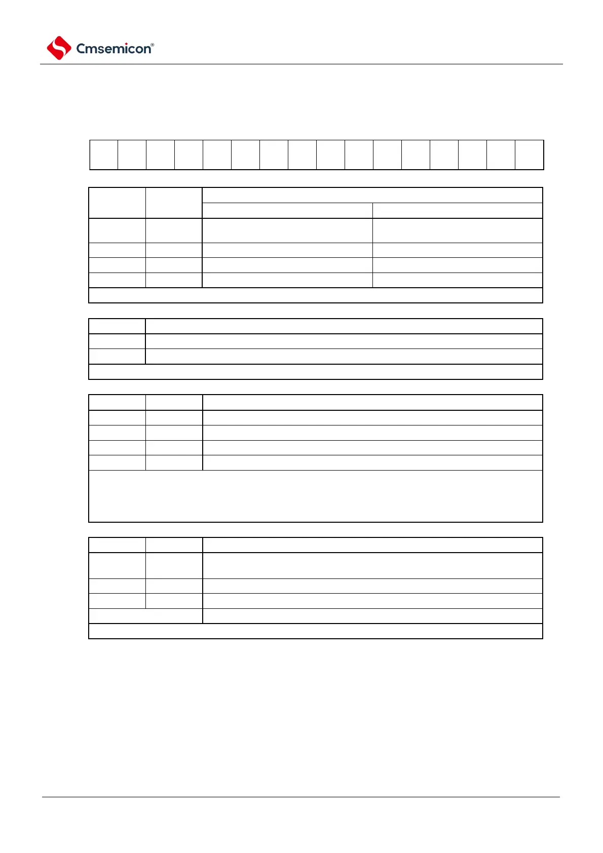
Figure 12-8 Format of serial communication operation setting register mn (SCRmn) (2/2)
Address: 40041118H(SCR00)~4004111EH(SCR03) After reset: 0087HR/W
40041558H(SCR10)~4004155AH(SCR13)
Symbol
15 14 13 12 11 10 9 8 7 6 5 4 3 2 1 0
SCRmn
Setting of parity bits in UART mode
Parity bits are not output.
There is no parity at the time of
reception.
In SSPI mode and Simplified I
2
C mode, both the PTCmn1 bit and the PTCmn0 bit must be set to 0.
Selection of data transfer order in SSPI and UART modes
Performs MSB-priority input/output.
Perform LSB-priority input/output.
In Simplified I
2
C mode, the DIRmn bit must be 0.
Setting of the stop bit in UART mode
Stop bit length = 2 bits (limited to mn=00, 02, 10).
If an end-of-transfer interrupt is selected, an interrupt occurs after all stop bits have been transferred.
When UART is received or in Simplified I
2
C mode, it must be set to 1 stop bit (SLCmn1, SLCmn0=0, 1).
In SSPI mode, it must be set to no stop (SLCmn1, SLCmn0=0, 0).
When UART is sent, it must be set to 1 bit (SLCmn1, SLCmn0=0, 1) or 2 bits (SLCmn1, SLCmn0=1, 0).
Setting of data length in SSPI and UART modes
9 bits of data length (saved in bit0~8 of the SDRmn register) (selectable only in
UART mode).
7 bits of data length (saved in bit0 to 6 of the SDRmn register).
8 bits of data length (bit0 to 7 in the SDRmn register).
In Simplified I
2
C mode, both the DLSmn1 bit and the DLSmn0 bit must be set to 1.
Note 1 Limited to SCR00, SCR02, SCR10 registers only.
2. Limited to SCR00 register and SCR01 register, the others are fixed as 1.
3. Nothing to do with the content of the data, always appended 0.
Notice Bit 3, 6, and 11 must be set to "0" (also bit 5 of the SCR01, SCR03, and SCR11 registers must be set to "0"), and
bit 2 must be set to "1".
Remark m: Unit number (m=0, 1) n: channel number (n=0~3) p: SSPI number (p=00, 01, 10, 11, 20, 21)