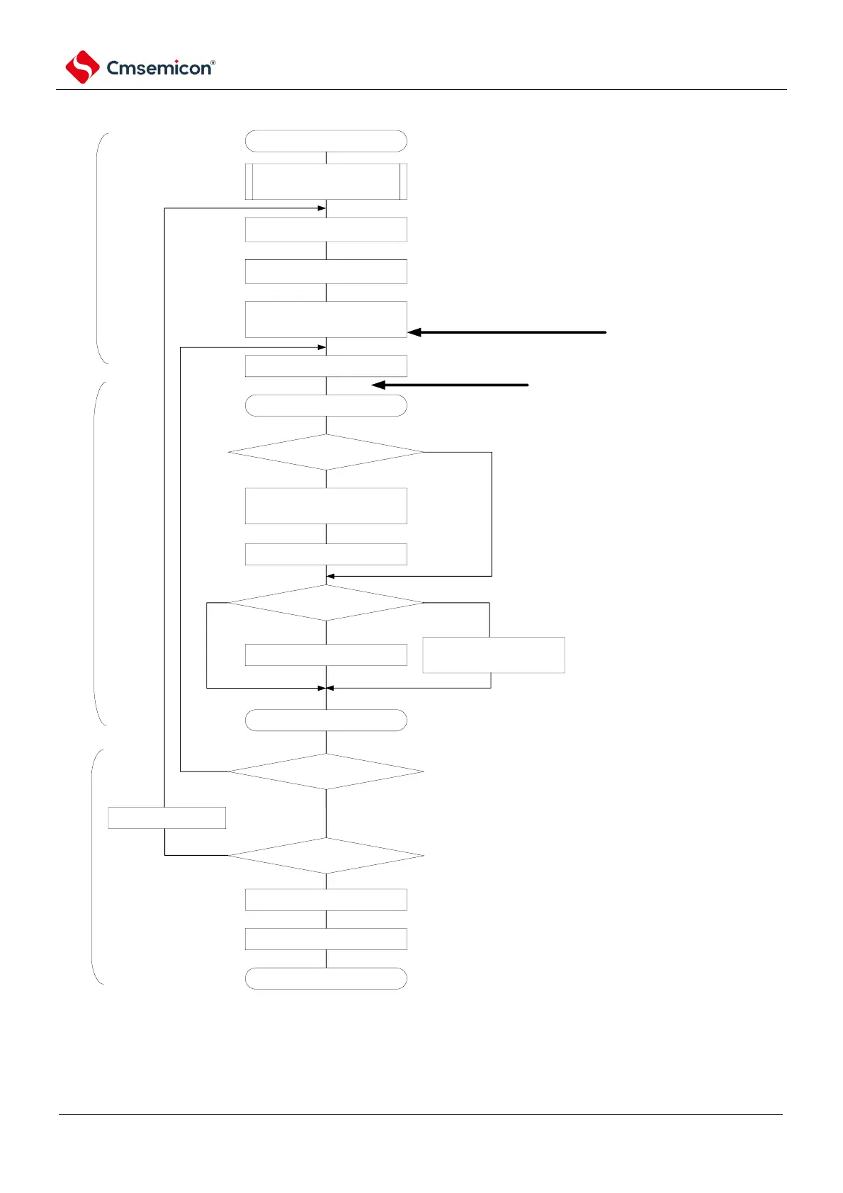
SSPI communication starts
configure transmit and receive
data
enable interrupt
write transmit data into
SIOp(=SDRmn[7:0])
wait for transmitting and reception
completes.
relevant initial configuration, refer to diagram
19~42(select buffer empty interrupt)
regarding transmit data, configure storage region and
data count (via software, any specified internal RAM
storage region, transmit data pointer communnication
data count)
after clear interrupt request flag(Ifxx) and release interrupt
mask(MKxx), enable interrupt
output SDOp and SCLKp
signal (start communication)
via writing into SIOp.
if there is data to be transmitted (communication data count
>=2), then read data from storage region and write into SIOp,
update storage pointer. If transmit completes
(communication data count = 1), then modify bit of transmit
completion interrupt.
SCI initial configuration
buffer empty/transmit completion
interrupt
BFFmn=1?
read receiving data to
SIOp(=SDRmn[7:0])
RETURN
communication data count =0?
disable interrupt (mask).
set STmn bit to 1.
communication completed.
Yes
No
No
Yes
main program
interrupt process program
main program
if buffer empty or transmit completion
interrupt occurs, jump to interrupt
process program.
communication data count -1
continue communicating?
write MDmn 0 bit to 1
communication data count?
write MDmn 0 bit to 0
write transmit data into
SIOp(=SDRmn[7:0])
Yes
=0
2
=1
No
from reserved region read and transmit data
and write to SIOp, update transmit data pointer
except 1st interrupt, read received data
and write into storage region, update
receive data pointer