CMS32L051 User Manual |Chapter 12 Universal Serial Communication Unit
www.mcu.com.cn 355 / 703
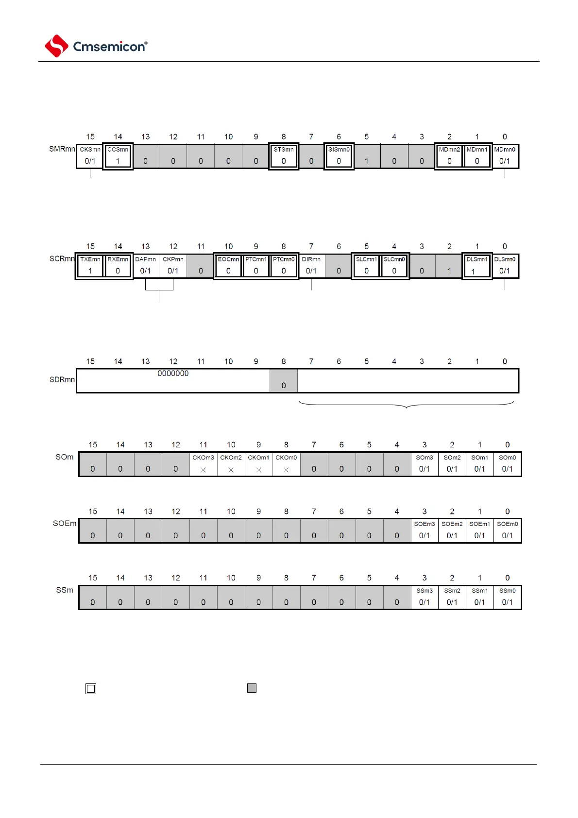
(1) Register setting
Figure 12-47 3 wire serial I/O (SSPI00, SSPI01, SSPI10, SSPI11, SSPI20, SSPI21)
Example of register settings at the time of slave transmission
(a) serial mode register mn (SMRmn)
(b) serial communication operation configuration registermn mn(SCRmn)
(c) serial data regsiter mn (SDRmn) (low 8 bit: SIOp)
(d) serial output register m(SOm) ...Only configure bit of target channel
(e) serial output enable registerm (SOEm)only set bit of target channel to 1.
(f) serial channel start register m (SSm) Only set bit of target channel to 1.
channel n operational clock (fMCK)
0: SPSm register configured pre-scaler output clock CKm0
1: SPSm register configured pre-scaler output clock CKm1
interrupt source of channel n
0: Transmit completion interrupt
1: Buffer empty interrupt
data transmit sequence selection
0: perform MSB first input/output
1: perform LSB first input/output
data length configuration
0: 7 bit data length
1: 8 bit data length
data and clock phase selection (details refer to "19.3
control universal serial communication unit registers)
SIOp
baud rate configuration
configuration of transmit data
Note
Note Limited to SCR00 register and SCR01 register, the others are fixed as 1.
Note 1.m: Unit number (m=0, 1) n: Channel number (n=0~3)p: SSPI number (p=00, 01, 10, 11, 20, 21.) )
mn=00~03, 10~11
2. : Fixed in SSPI slave send mode. : Cannot be set (initial value).
×: This is the bit that cannot be used in this mode (set the initial value if it is not used in other modes either).
0/1: Set 0 or 1 according to the user's purpose.