CMS32L051 User Manual |Chapter 12 Universal Serial Communication Unit
www.mcu.com.cn 444 / 703
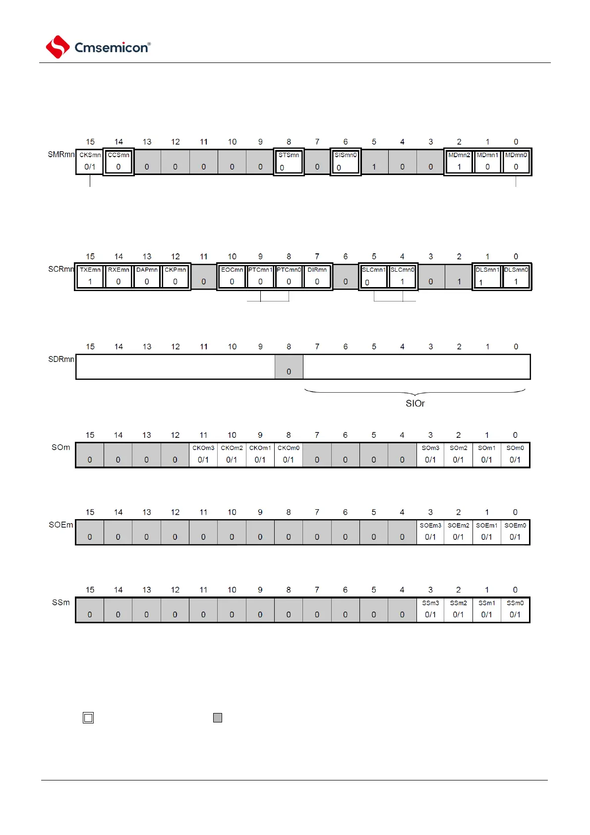
(1) Register setting
Figure 12-118 Example of register setting contents when sending address segments of Simple I2C
(IIC00, IIC01, IIC10, IIC11, IIC20, IIC21)
(a) serial mode register mn (SMRmn)
(b) serial communication operation configuration registermn mn(SCRmn)
(c) serial data regsiter mn (SDRmn) (low 8 bit: SIOr)
(d) serial output register m (Som)
(e)serial otuput enable register m (SOEm)
(f) serial channel start register m (SSm) Only set bit of target channel to 1.
generate start condition via operating Somn bit.
before generating start condition, SOEmn bit is '0', after generating start
condition, SOEmn bit is '1'.
channel n operational clock (fMCK)
0: SPSm register configured pre-scaler output clock CKm0
1: SPSm register configured pre-scaler output clock CKm1
Operation mode of channel n
0: Transmit completion interrupt
stop bit configuration
01B: append 1 bit (ACK)
parity check bit configuration
00B: no parity check
baud rate configuration configuration of transmit data(Address+R/W)
Note1 Note1
Note2 Note3
Note 1 Only for SMR00, SMR03, SMR11.
2. Limited to SCR00, SCR02, SCR10 only.
3. Limited to SCR00 register and SCR01 register, other fixed as 1.
Note 1.m: Unit number (m=0, 1) n: channel number (n=0~3)r: IIC numbers (r=00, 01, 10, 11, 20, 21 )
mn=00~03, 10~11
2. : Fixed in IIC mode. : Cannot be set (initial value).
×: This is the bit that cannot be used in this mode (set the initial value if it is not used in other modes either).
0/1: Set 0 or 1 according to the user's purpose.