CMS32L051 User Manual |Chapter 16 Enhanced DMA
www.mcu.com.cn 584 / 703
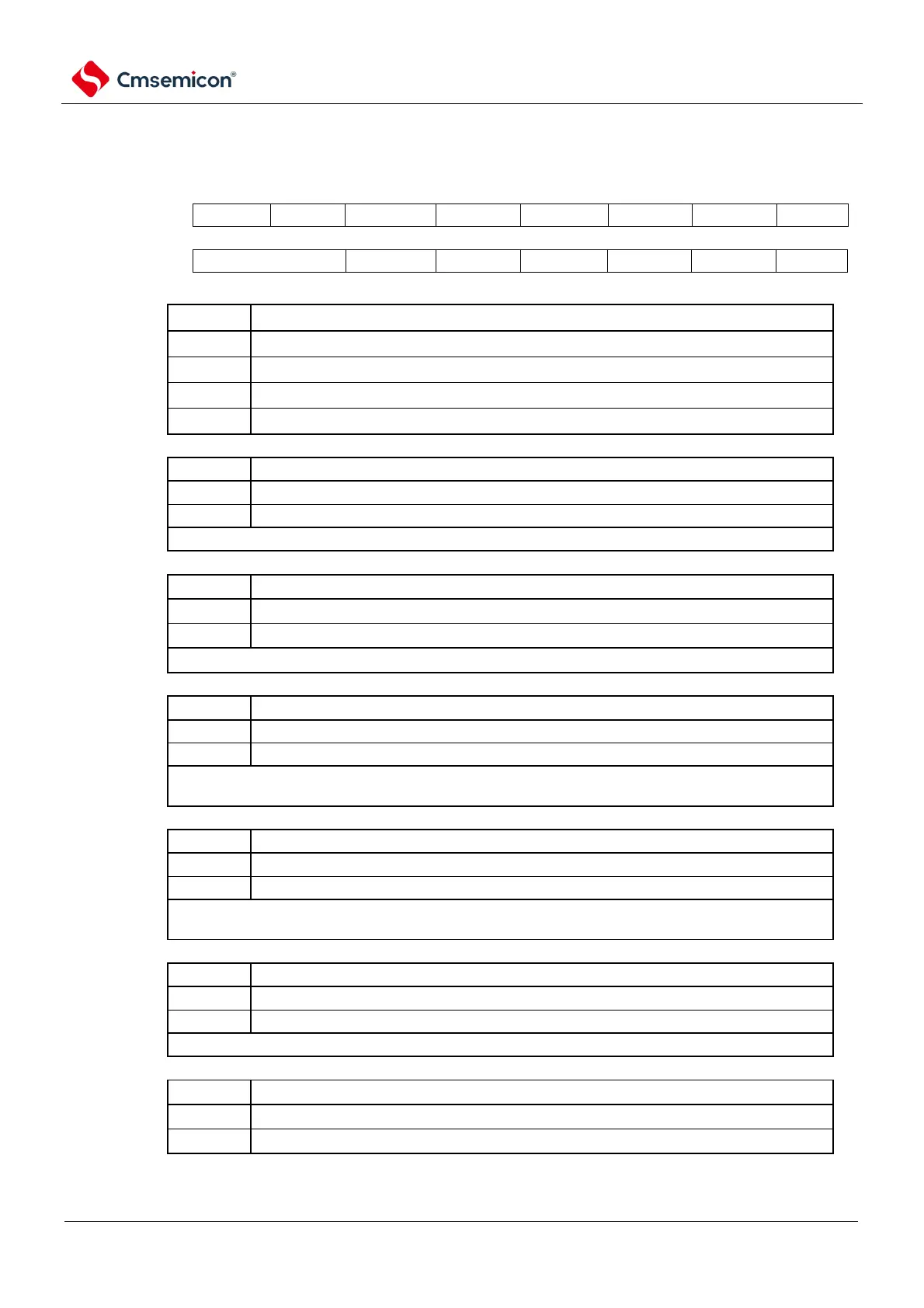
Figure 16-6 Format of DMA control register j (DMACRj)
Address:
Refer to 16.3.2
Control data allocation
. A
fter reset: Indefinite value
R/W
Selection of transmitted data length
Repeating pattern interrupts allow/disable
Interrupts are prohibited.
When the MODE bit is 0 (normal mode), the RPTINT bit is not set.
Allow/disallow for chain transfers
Chain transmission is prohibited.
The CHNE bit of the DMACR23 register must be 0 (chain transfer is prohibited).
Control of the transmitting destination address
When the MODE bit is 1 (repeat pattern) and the RPTSEL bit is 0 (the transfer target is the repeat
area), the DAMOD bit is not set.
Control of the transmitting source address
When the MODE bit is 1 (repeat pattern) and the RPTSEL bit is 1 (the delivery source is the repeat
region), the SAMOD bit is not set.
Selection of repeating areas
The delivery target is a repeating area.
The delivery source is a repeat.
When the MODE bit is 0 (normal mode), the setting of the RPTSEL bit is invalid.
Selection of transfer mode
Note DMACRj register cannot be accessed via DMA transfer.