CMS32L051 User Manual |Chapter 18 Interrupt Function
www.mcu.com.cn 612 / 703
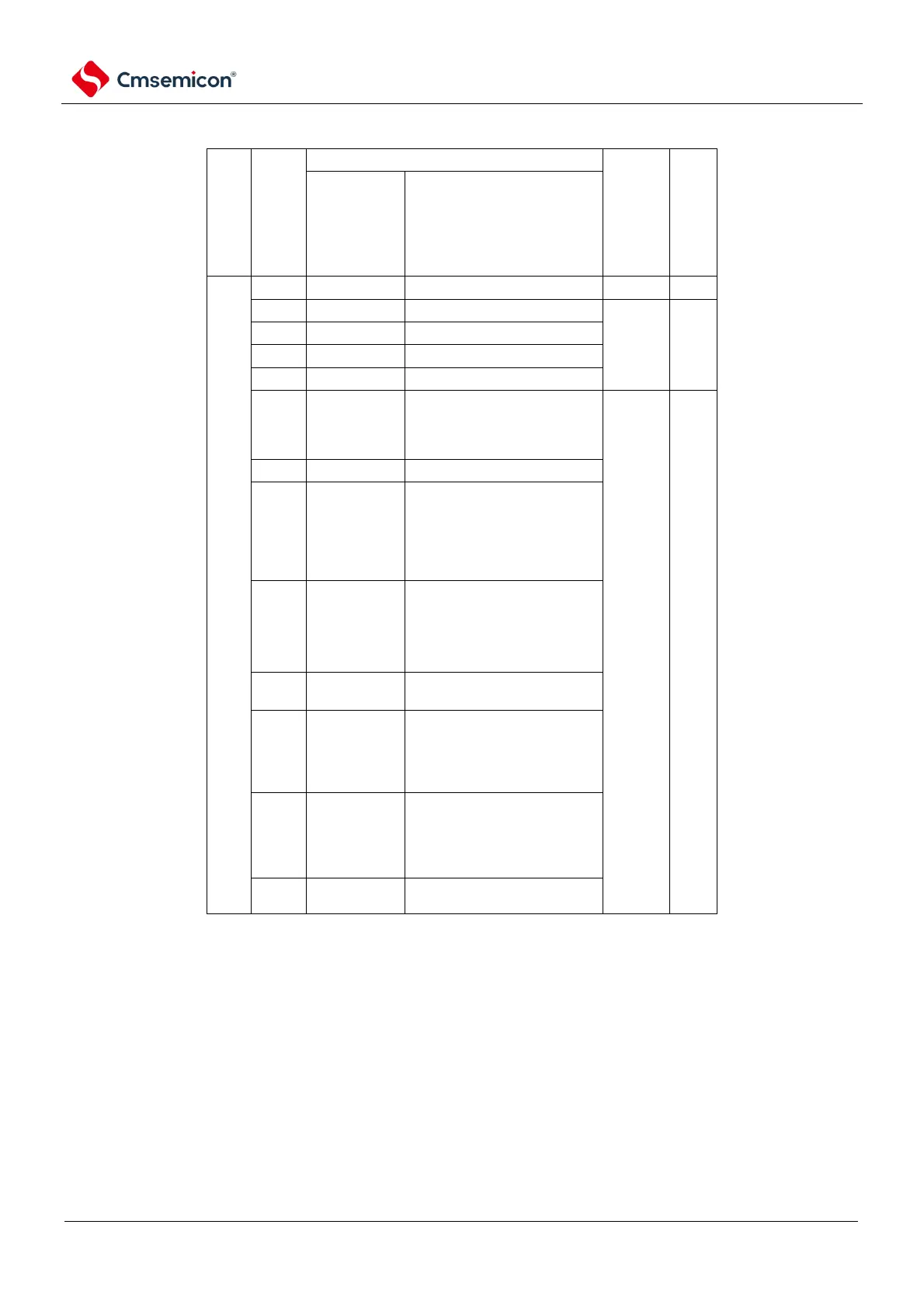
Table 18-1 List of interrupt sources (1/3)
The source of the
interrupt
numbering
The source of the interrupt
Basic structure
Type
Note 1
Detection of pin input edges
Detection of pin input edges
Detection of pin input edges
Detection of pin input edges
The counting end of timer
channel 01 or the end of the
capture (when the high 8-bit
timer is operating).
INTST2/
INTSSPI20/
INTIIC20
The end of the UART2
transmission or the end of the
transmission of the buffer null
interrupt/SSPI20 or the end of
the transmission of the buffer
null interrupt/IIC20
INTSR2/
INTSSPI21/
INTIIC21
The end of transmission
received by UART2 / the end
of transmission of SSPI21 or
the end of transmission of
buffer null interrupt/IIC21
A communication error
received by UART2 occurred
INTST0/
INTSSPI00/
INTIIC00
The end of the UART0
transmission or the end of the
buffer null interrupt/SSPI00 or
the end of the buffer null
interrupt/IIC00 transfer
INTSR0/
INTSSPI01/
INTIIC01
The end of transmission
received by UART0 / the end
of transmission of SSPI01 or
the end of transmission of
buffer null interrupt/IIC01
A communication error
received by UART0 occurred
Note 1. The basic composition types (A) to (C) correspond to Figure 18-1 (A)~(C).
2. This is when bit7 (LVIMD) of the voltage sense level register (LVIS) is set to 0.