EasyManua.ls Logo

Cmsemicon CMS32L051 - Page 654

Default Icon
703 pages
Print Icon
To Next Page IconTo Next Page
To Previous Page IconTo Previous Page
Loading...
V1.2.2
CMS32L051 User Manual |Chapter 23 Voltage Detection Circuit
www.mcu.com.cn 654 / 703
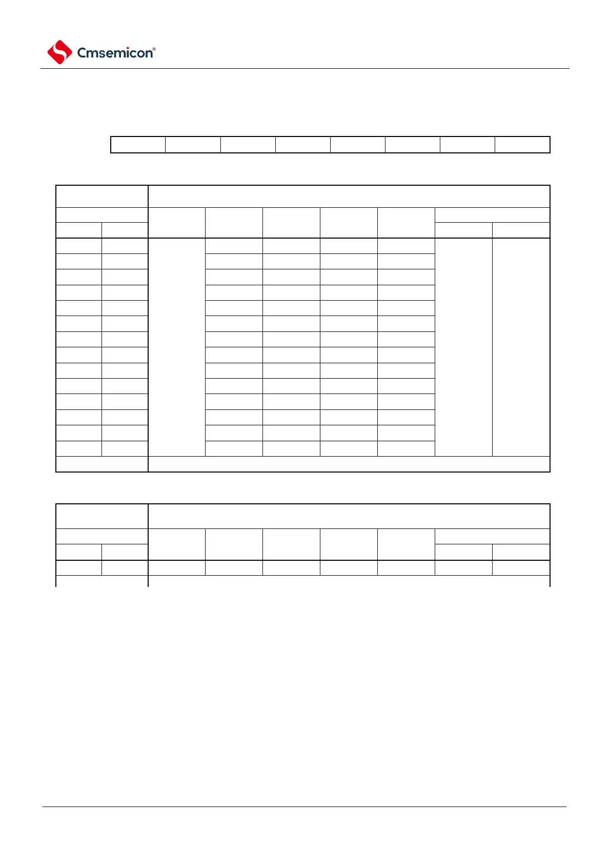
Table 23-1 Format of user option bytes (000C1H) (2/2)
Address: 000C1H
7 6 5 4 3 2 1 0
VPOC2
VPOC1
VPOC0
1
LVIS1
LVIS0
LVIMDS1
LVIMDS0
 LVD setting (interrupt mode)
Detection
voltage
Setting value of the option byte
V
LVD
VPOC2
VPOC1
VPOC0
LVIS1
LVIS0
Mode setting
rise
decline
LVIMDS1
LVIMDS0
1.67V
1.63V
0
0
0
1
1
0
1
1.77V
1.73V
0
0
1
0
1.88V
1.84V
0
1
1
1
1.98V
1.94V
0
1
1
0
2.09V
2.04V
0
1
0
1
2.50V
2.45V
1
0
1
1
2.61V
2.55V
1
0
1
0
2.71V
2.65V
1
0
0
1
2.81V
2.75V
1
1
1
1
2.92V
2.86V
1
1
1
0
3.02V
2.96V
1
1
0
1
3.13V
3.06V
0
1
0
0
3.75V
3.67V
1
0
0
0
4.06V
3.98V
1
1
0
0
Values other than those above are prohibited.
LVD is OFF (Use RESETB External reset of the pin)
Note 1 You must write 1 to bit4.
2. When the supply voltage rises, the reset state must be maintained by the voltage detection circuit or external reset
before the supply voltage reaches the working voltage range shown in the AC characteristics of the data sheet;
When the supply voltage drops, it must be reset through deep sleep mode transfer, voltage detection circuitry, or
external reset before the supply voltage drops below the operating voltage range.
The operating voltage range depends on the setting of the user option byte (000C2H).
Note 1 ×: Ignore
2. The detection voltage is TYP Value. For details, please refer to the LVD circuit characteristics in the data sheet.
Detection
voltage
The setting value of the option byte
V
LVD
VPOC2
VPOC1
VPOC0
LVIS1
LVIS0
Mode setting
rise
decline
LVIMDS1
LVIMDS0
1
×
×
×
×
×
1
Values other than those above are prohibited.

Table of Contents

Related product manuals