CMS32L051 User Manual |Chapter 23 Voltage Detection Circuit
www.mcu.com.cn 658 / 703
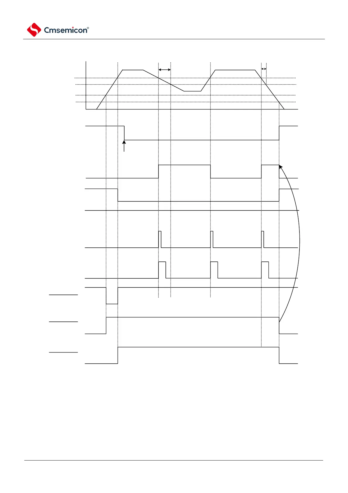
Figure 23-5 Generation timing of interrupt signals (option bytes LVIMDS1, LVIMDS0=0, 1)
Note 1 After the reset signal is generated, the LVIMK flag changes to 1.
2. When the operating voltage drops, it must be set to the reset state by transferring or externally resetting the
operating voltage below the operating voltage range shown in the AC characteristics of the data sheet. During
restart operation, it must be confirmed that the supply voltage returns to the operating voltage range.
Note V
POR
: The POR supply voltage rise detection voltage
V
PDR
: The POR supply voltage drop detection voltage