CMS32L051 User Manual |Chapter 4 Clock Generation Circuit
www.mcu.com.cn 66 / 703
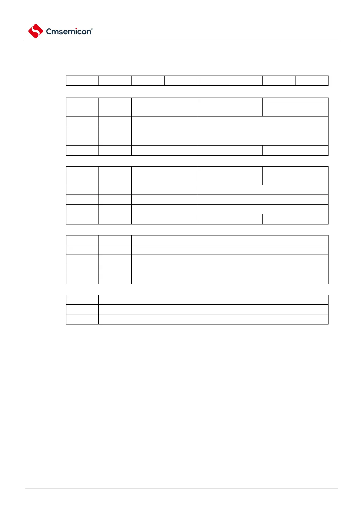
Figure 4-2 Format of clock operating mode control register (CMC)
Address: 40020400H After reset: 00H R/W
Symbol
7 6 5 4 3 2 1 0
Cmc
Note: The EXCLKS bit, OSCSELS bit, AMPHS 1 bit, and AMPHS0 bits are only initialized on power-on reset and remain
unchanged on other resets.
Note 1. After the reset is released, the CMC register can only be written once via the 8-bit memory operation command.
When using the CMC register at the initial value (00H), in order to prevent malfunction when the program is out of
control (it cannot be recovered if a value other than 00H is miswritten), the CMC register must be set after the
reset is released 00H.
2. The CMC register must be set after the reset is released and before the X1 or XT1 oscillation is started by setting
the clock operating state control register (CSC).
3. When the X1 clock oscillation frequency exceeds 10MHz, the AMPH position must be 1.
4. The AMPH bit, the AMPHS1 bit and the AMPHS0 bit must be set after the reset has been released and with fIH
selected as the state of f
CLK
(before switching f
CLK
to f
MX
or f
SUB
).
5. The oscillation settling time of f
XT
must be counted by software.
6. The upper frequency limit of the system clock is 64 MHz, but the upper frequency limit of the X1 oscillation circuit
is 20 MHz.
Note f
X
: X1 clock oscillation frequency