CMS32L051 User Manual |Chapter 23 Voltage Detection Circuit
www.mcu.com.cn 660 / 703
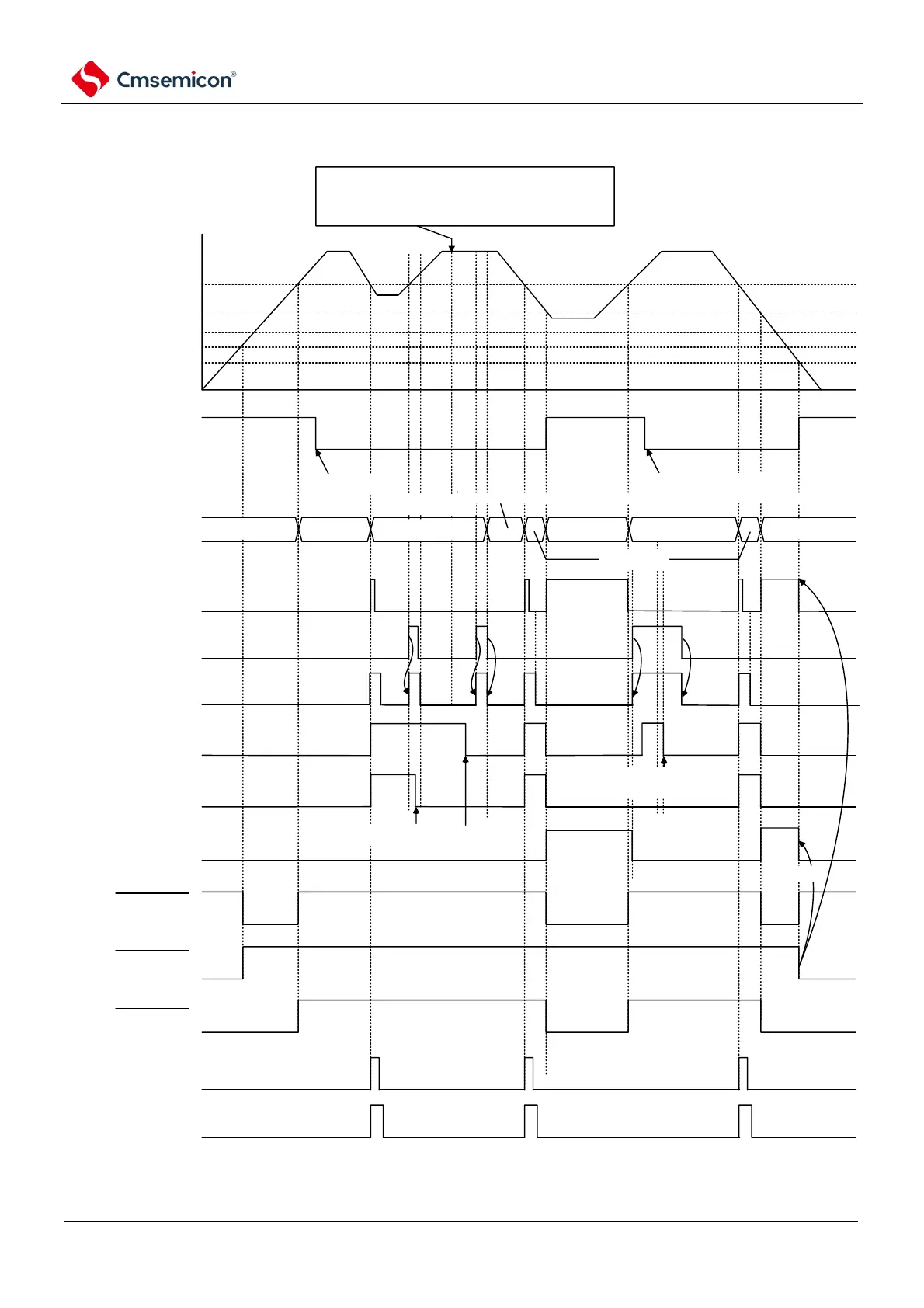
Figure 23-6 Generation timing of reset & interrupt signal (LVIMDS1 for option bytes, LVIMDS0=1, 0) (1/2)
note 1
H
low limit of working
voltage range
VPOR=1.51V(TYP.)
VPDR=1.50V(TYP.)
power supply voltage(VDD)
VLVD
L
VLVDH
LVIMK flag
(via software
configuration )
reset
normal
operation
reset
normal
operation
reset
clear via
software
clear via software
normal
operation
push stack
operation
}
wait for stablization via software (400us or 5 clock cycles (fIL))
note 3
operation
status
LVIF flag
LVISEN flag
(via software
configuration )
LVIOMSK flag
LVIMD flag
LVILV flag
LVIRF flag
internal reset signal
POR reset signal
LVD reset signal
INTLVI
LVIIF flag
Time
Clear
Clear
clear via software
note 2
clear via software
note 3
push stack
operation
if after release mask no reset is generated, then it can
be tell that VDD has recovered to value VLVDH.
After LVIMD bit cleared, transfer can be perform
normally.