high speed system
clock
high speed internal
oscillation clock
secondary system
clock
switching via
software
at least
10us
low limit of working voltage range
VPOR
voltage of power source (VDD)
power on reset signal
RESETB pin
CPU clock
high speed internal
oscilator clock (fIH)
high speed system clock
(fMX) (Scenario of
selecting X1 oscilation)
secondary system clock
(fsub) (Scenario of
selecting XT1 oscilation)
Configure XT1 to start
oscilating via software
Configure X1 to start
oscilating via software
X1 clock oscilation
stablization time.
Note 1
reset
process
0V
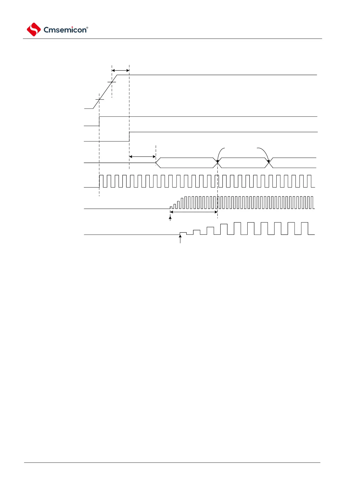
① After the power is turned on, an internal reset signal is generated through a power-on reset
(POL) circuit.
However, the reset state is maintained by voltage detection circuitry or an external reset until
the operating voltage range shown in the AC characteristics of the data sheet is reached (the
figure above is an example when using an external reset).
② If the reset is released, the high-speed internal oscillator automatically begins to oscillate.
③ After the reset is released, a voltage stabilization wait and reset process occurs, and then the
CPU starts operating with a high-speed internal oscillator clock.
④ The X1 clock or the starting oscillation of the XT1 clock must be set via software (see Example
of setting up a 4.6.2 X14.6.2 Example of setting up an X1 oscillation circuit and 4.6.3).4.6.3
Example of setting up an XT1 oscillation circuit).
⑤ If you want to switch the CPU clock to the X1 clock or the XT1 clock, you must switch through
the software settings after waiting for the clock oscillation to stabilize (see the 4.6.2 X1
4.6.2Example of setting up an X1 oscillation circuitand 4.6.3Example of setting up an XT1
oscillation circuit).
Note 1 When the reset is released, the oscillation settling time of the X1 clock must be confirmed through the status
register (OSTC) of the oscillation settling time counter.
Note that if an external clock is used for the EXCLK pin input, there is no need for oscillation stabilization wait times.